Lock structure for locking male and female connector housings together

a technology for locking connectors and housings, applied in the direction of electrical apparatus, connection, coupling device connections, etc., can solve the problems of incongruous operation and drawbacks of connecting devices, and achieve the effect of good operation and positive locking

Inactive Publication Date: 2001-12-04
YAZAKI CORP
View PDF9 Cites 36 Cited by
  • Summary
  • Abstract
  • Description
  • Claims
  • Application Information

AI Technical Summary

Benefits of technology

It is therefore an object of this invention to provide a lock structure in which a sensation of good operation can be obtained when achieving a locked condition, and the locking can be effected positively.
According to the invention, there is provided a lock structure comprising a male connector housing, a female connector, an elastic lock arm, a lock-retaining portion and a correction portion. The female connector housing is to be fitted with the male connector housing in an opposing manner. The elastic lock arm is provided on one of the male and female connector housings and has a lock projection. The lock-retaining portion is provided on the one of the male and female connector housings that is not provided with the elastic lock arm. The lock projection of the lock arm is engageable with the lock-retaining portion. The correction portion corrects elastic deformation of the lock arm when the male and female connector housings are fitted together.
At this time, even if the lock arm is elastically deformed upon application of an external force, the correction portion corrects the elastically-deformed lock arm into its original position when the male and female connector housings are fitted together. The lock arm is therefore properly flexed, so that the lock projection engages with the lock-retaining portion. As a result, a sensation of good operation can be obtained when achieving the locked condition, and a positively-locked condition can be obtained.
In this lock structure, when the male connector housing is inserted into the female connector housing, with the lock arm kept elastically deformed upon application of an external force, the correction receiving portion of the lock arm slides in contact with the correction portion, so that the lock arm is corrected into the normal position. As a result, the lock projection is engaged with the lock-retaining portion in a proper condition, and therefore a sensation of good operation can be obtained when achieving the locked condition, and a positively-locked condition can be obtained.

Problems solved by technology

However, connectors such as the one shown in FIG. 13 suffer from drawbacks.
There may be a sensation of incongruous operation, as compared with an ordinary operation.

Method used


Image

  • Lock structure for locking male and female connector housings together
  • Lock structure for locking male and female connector housings together
  • Lock structure for locking male and female connector housings together

Examples


first embodiment

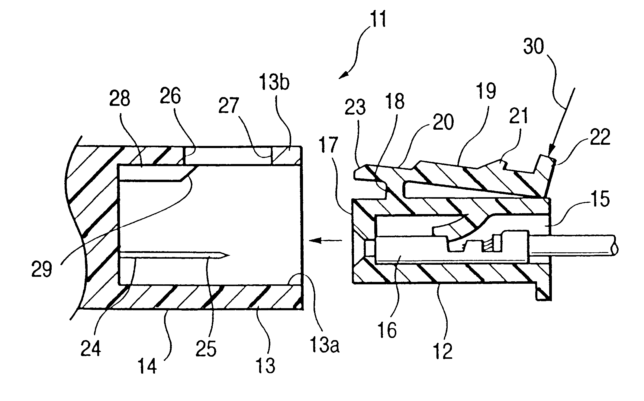
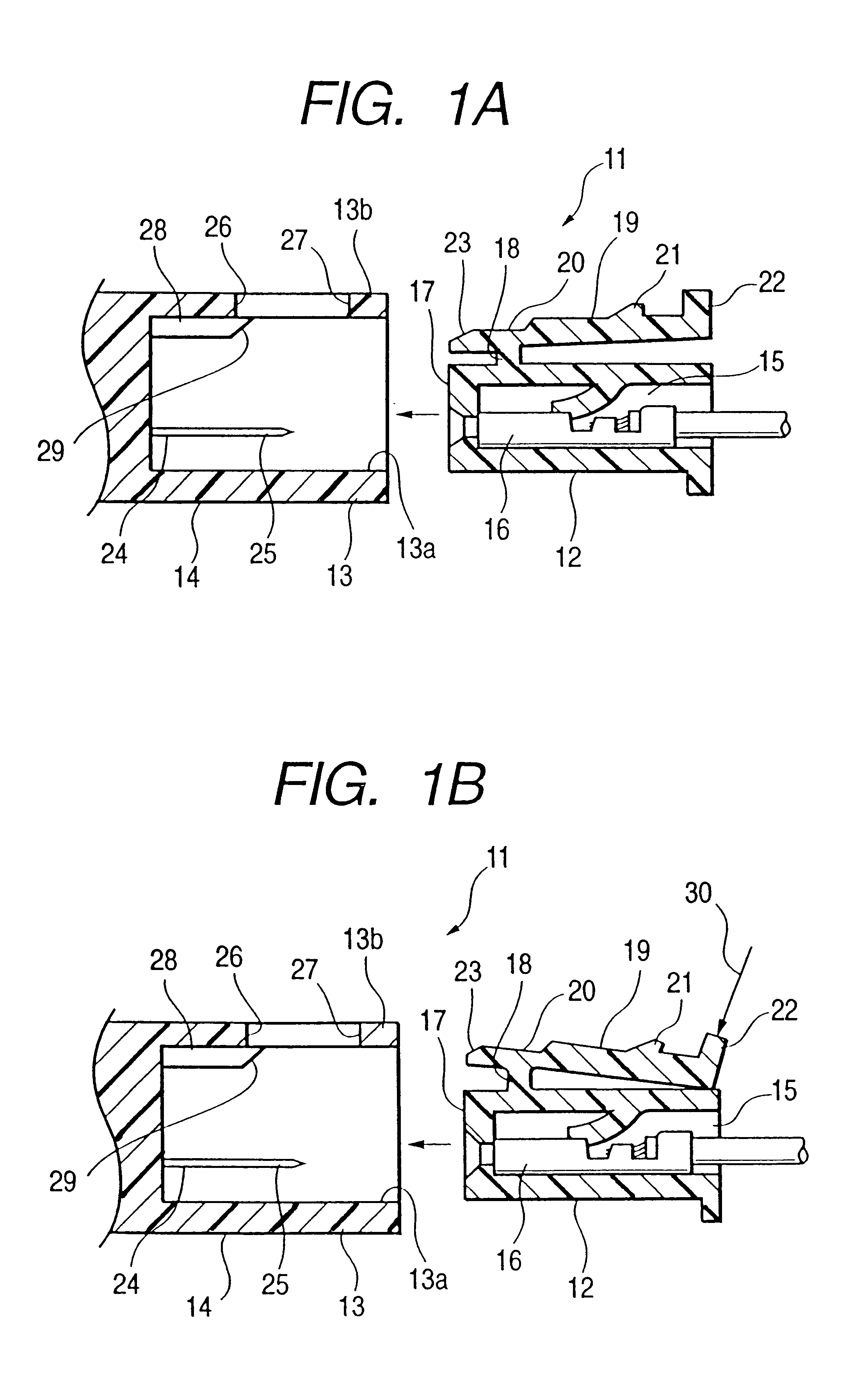
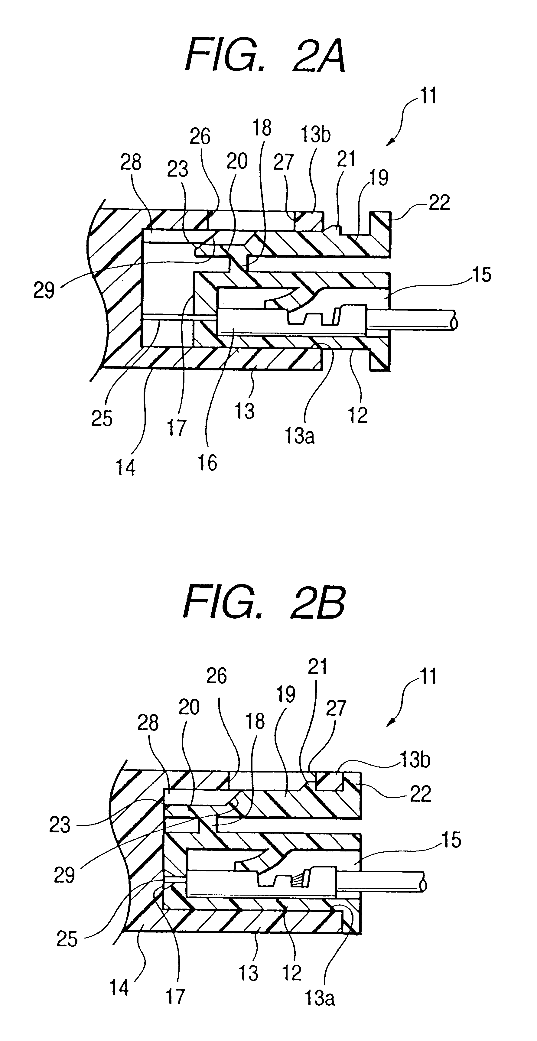
FIGS. 1 to 4 show a connector 11 using a lock structure of the invention. As shown in FIG. 1, the connector 11 comprises a male connector housing 12, and a female connector housing 14 having a hood portion 13 into which the male connector housing 12 is inserted and fitted. Terminal receiving chambers 15 are formed within the male connector housing 12, and female terminals 16 are received in these terminal receiving chambers 15, respectively. An elastic lock arm 19 is integrally formed on a portion of the male connector housing 12 via a support portion 18 near a fitting side 17, to be inserted into the hood portion 13. A correction receiving portion 20 is formed at one end portion of the lock arm 19. A lock projection 21 is formed on that portion of the lock arm 19, and is disposed rearwardly of the correction receiving portion 20 and the support portion 18. An operating portion 22 is formed at an end of the lock arm 19 at the side of the lock projection 21. As shown in FIG. 3, the c...

second embodiment

Next, a second embodiment will be described with reference to FIGS. 5A and 5B. A connector 32 of this embodiment differs from the connector of the preceding embodiment in that a male connector housing 33 has a lock arm 34 of a different shape. More specifically, in the preceding embodiment, as shown in FIG. 1, the lock arm 19 is supported at an intermediate portion thereof by the support portion 18, and therefore is the so-called see-saw type lock arm. On the other hand, the lock arm 34 of this embodiment is the cantilever-type lock arm, which extends from a fitting side 17 of the male connector housing 33.

As shown in FIGS. 5A and 5B, the lock arm 34 in this embodiment is formed integrally on the male connector housing 33 at the fitting side 17 through a support portion 35, and is supported in a cantilever manner. A correction portion insertion hole 36 is formed through the support portion 35.

A correction portion 38 is formed on and extends from a bottom (i.e., inner end) 37 of a ho...

fourth embodiment

Next, a fourth embodiment will be described with reference to FIGS. 7 to 12. A connector 51 of this embodiment comprises a male connector housing 52, and a female connector housing 54 having a hood portion 53 into which the male connector housing 52 is inserted and fitted. As in the above embodiments, a plurality of terminal receiving chambers 55 (see FIG. 11) are formed within the male connector housing 52, and female terminals (not shown) are received in these terminal receiving chambers, respectively.

As shown in FIGS. 11 and 12, a pair of side walls 52a and 52a is formed and projects from an outer surface of the male connector housing 52. The side walls 52a and 52a are spaced at a predetermined distance from each other. A lock arm 59 is provided between the two side walls 52a and 52a. The lock arm 59 is supported integrally on the pair of side walls 52a and 52a through support arms 58 and 58 (see FIG. 12) at a front end of the pair of side walls 52a and 52a disposed forwardly in ...


PUM


Abstract

A lock structure comprising a male connector housing, a female connector, an elastic lock arm, a lock-retaining portion and a correction portion. The female connector housing is to be fitted with the male connector housing in an opposing manner. The elastic lock arm is provided on one of the male and female connector housings and has a lock projection. The lock-retaining portion is provided on the one of the male and female connector housings that is not provided with the elastic lock arm. The lock projection of the lock arm is engageable with the lock-retaining portion. The correction portion corrects elastic deformation of the lock arm when the male and female connector housings are fitted together.

Description

BACKGROUND OF THE INVENTION1. Field of the InventionThis invention relates to a lock structure for locking or holding a condition in which male and female connector housings mutually fit together.2. Description of the Related ArtFIG. 13 shows a connector 1 (disclosed in Japanese Utility Model Unexamined Publication No. 56-7287) using a lock device. In this Figure, this connector 1 comprises a male connector housing 2, and a female connector housing 4 having a hood portion 3 into which the male connector housing 2 is inserted and fitted. The male connector housing 2 has an elastic lock arm 6 supported thereon in a cantilever manner on a fitting side 5 of the housing. A lock projection 7 is formed on the lock arm 6 at an intermediate portion thereof, and an operating portion 8 is provided at a free end of the lock arm 6.A groove 9 for receiving the lock arm 6 is formed in the hood portion 3 of the female connector housing 4, and a retaining member 10, extending between opposite sides ...

Claims


Application Information

Patent Timeline
Patent Type & Authority Patents(United States)
IPC IPC(8): H01R13/627H01R13/639
CPCH01R13/6272
Inventor FUKUDA, MASARUOHSUMI, HIDEKI
Owner YAZAKI CORP
Why Eureka
Try Eureka