
Methods for use in dental articulation

a technology for dental articulation and articulation, applied in the field of dental articulation, can solve the problems of time-consuming articulation technique, high cost of mechanical articulators, and other mechanical articulators that are more complex

Inactive Publication Date: 2001-11-27
3M INNOVATIVE PROPERTIES CO
View PDF92 Cites 438 Cited by
  • Summary
  • Abstract
  • Description
  • Claims
  • Application Information

AI Technical Summary

Benefits of technology

The present invention in its various embodiments is highly advantageous for the dental practitioner, because the articulation can be carried out using a computing system in conjunction with digital dental image data so that neither models of the patient's upper and lower dental arches nor a mechanical articulator such as described above is needed. The present invention enables the practitioner to study the patient's occlusion so that any necessary corrections can be provided to establish proper occlusal contacts and optimum cusp / fossa relationships between the teeth of the patient's upper and lower dental arches as well as providing other advantages that will be apparent to one skilled in the art from the description provided herein.

Problems solved by technology

Other mechanical articulators are more complex and may include mechanisms that are adjustable in various planes to simulate lateral and protrusive mandibular movement.
As can be appreciated, however, the technique of articulation that is described above is time consuming and must be carefully executed to ensure that the resulting articulation properly simulates motion of the patient's jaws.
Mechanical articulators are also costly, and the more complex articulators sometimes require factory readjustment to ensure that the coupling of the upper member to the lower member of the articulator is properly calibrated.
Such condyle geometry data provides limitations on the movement of at least the lower arch image when the arch images are displayed and manipulated to move at least the lower arch image relative to the upper arch image and the reference hinge axis.

Method used


Image

  • Methods for use in dental articulation
  • Methods for use in dental articulation
  • Methods for use in dental articulation

Examples


Embodiment Construction

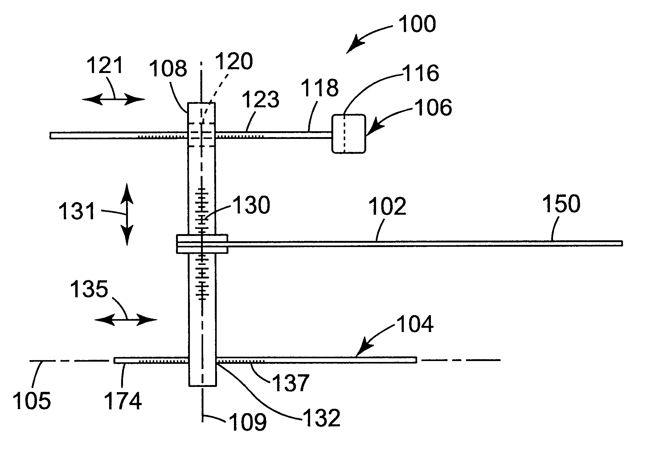
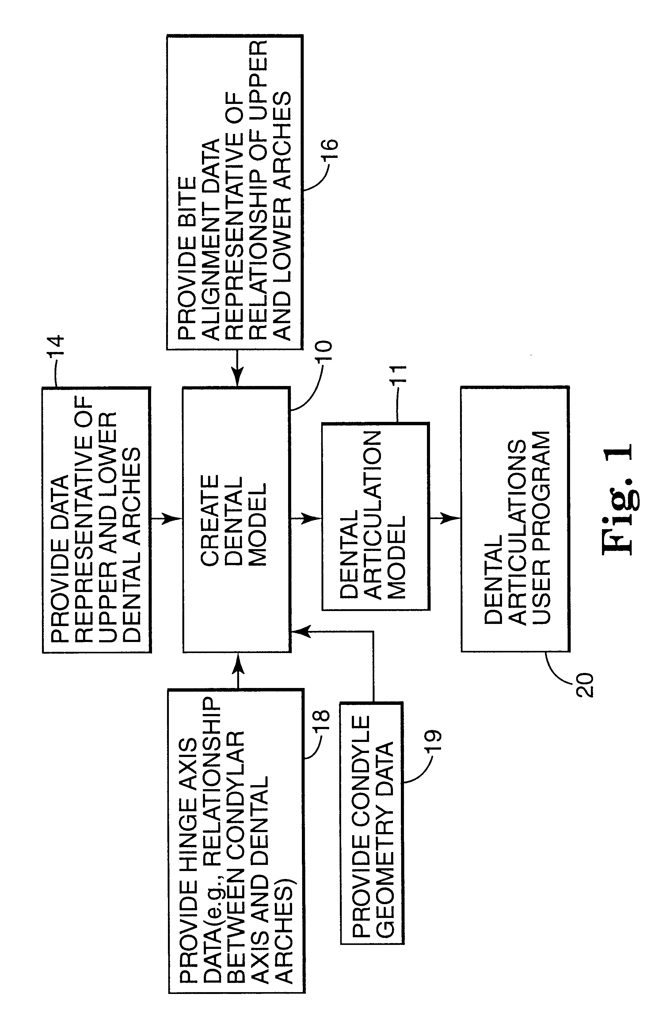
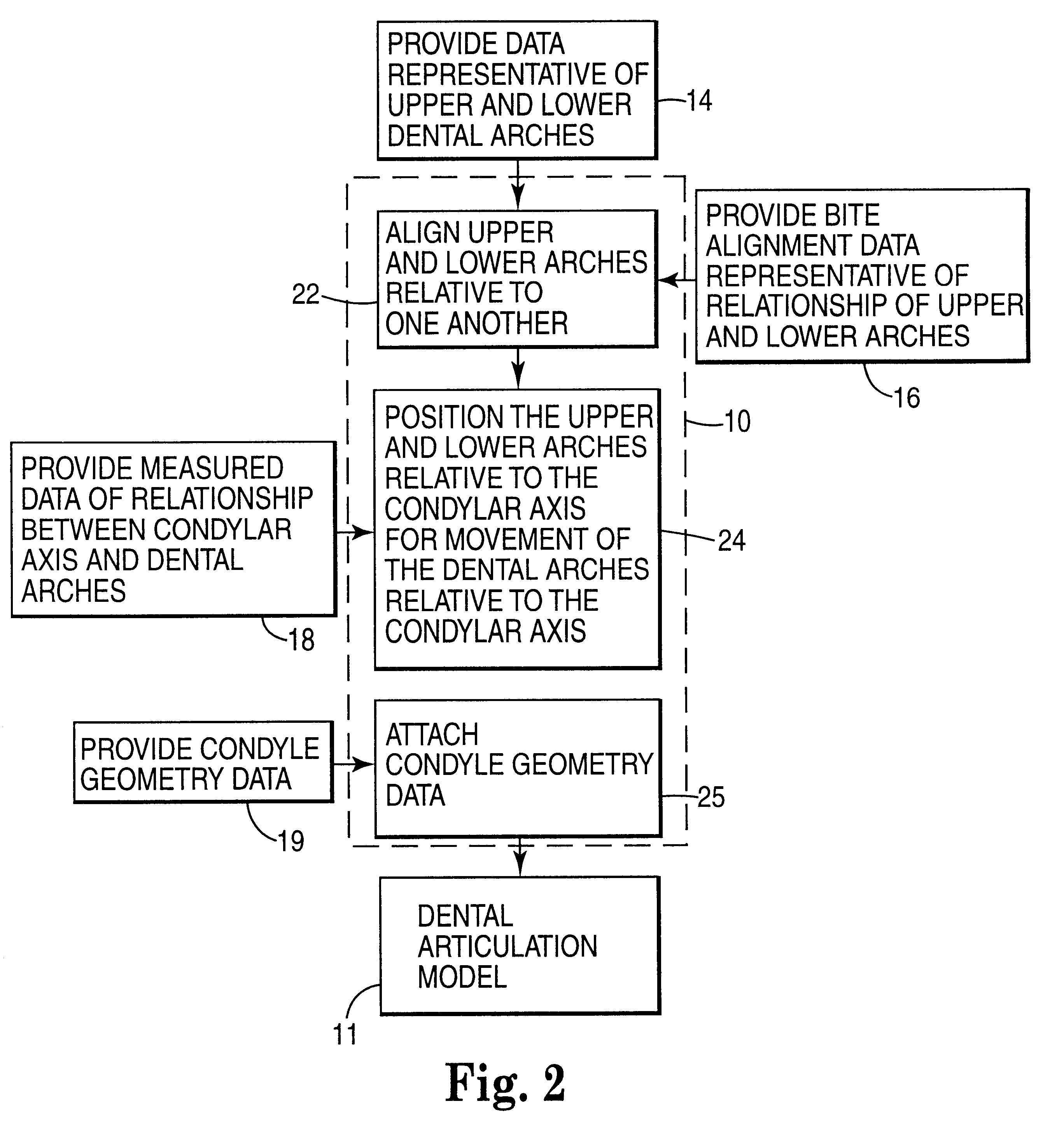
The present invention shall be described generally with reference to FIGS. 15. Thereafter, the present invention shall be described in further detail with reference to FIGS. 6-16.

As used herein, the terms given below are defined as follows. Bite registration is defined as the location of the upper and lower dental arches of a patient in occlusion (e.g., maximum intercuspation). The occlusal relationship may be based on first point of contact or based on other degrees of interdigitation of the upper and lower dental arches such as interdigitation for providing maximum intercuspation or to a controlled point of contact between the upper and lower dental arches which avoids mandibular shifting (e.g., shifting which may be due to occlusal prematurity).

Articulation is defined as bite registration in addition to the relationship of the upper and lower dental arches to the condyle axis of the patient. Articulation may occur either as simple hinge motion (i.e., simple hinge articulation) ab...


PUM


Abstract

A computer implemented method of creating a dental model for use in dental articulation includes providing a first set of digital data corresponding to an upper arch image of at least a portion of an upper dental arch of a patient, providing a second set of digital data corresponding to a lower arch image of at least a portion of a lower dental arch of the patient, and providing hinge axis data representative of the spatial orientation of at least one of the upper and lower dental arches relative to a condylar axis of the patient. A reference hinge axis is created relative to the upper and lower arch images based on the hinge axis data. Further, the method may include bite alignment data for use in aligning the lower and upper arch images. Yet further, the method may include providing data associated with condyle geometry of the patient, so as to provide limitations on the movement of at least the lower arch image when the arch images are displayed. Further, a wobbling technique may be used to determine an occlusal position of the lower and upper dental arches. Various computer implemented methods of dental articulation are also described. For example, such dental articulation methods may include moving at least one of the upper and lower arch images to simulate relative movement of one of the upper and lower dental arches of the patient, may include displaying another image with the upper and lower dental arches of the dental articulation model, and / or may include playing back recorded motion of a patient's mandible using the dental articulation model.

Description

The present invention relates to dental articulation. More particularly, the present invention pertains to methods for use in dental articulation which use digital data that corresponds to images of a patient's upper and lower dental arches.DESCRIPTION OF THE RELATED ARTDentists, orthodontists, prosthodontists and others engaged in various fields of dentistry often have use for a model or replica of selected areas of a patient's oral cavity. For example, a dentist or prosthodontist may desire to have a model of an area of a patient's oral cavity where one or more teeth are missing or damaged, so that suitable replacement teeth may be made in the lab using the model as a guide. In practice, the replacement teeth may be fitted by trial and error on the model and adjusted in size and shape as needed until a satisfactory size and shape are attained.As another example, orthodontists often use models of a patient's teeth to study malformations of the teeth and jaws and plan a course of tr...

Claims


Application Information

Patent Timeline
Patent Type & Authority Patents(United States)
IPC IPC(8): A61C11/00A61C7/00A61C9/00A61B19/00A61C13/00A61C19/045
CPCA61C11/00A61C13/0004A61C7/002A61C9/004A61C9/0046A61C13/0003
Inventor JORDAN, RUSSELL A.HANSEN, JAMES D.CARUSO, JOSEPH M.DUFOUR, PATRICK B.NISSENBAUM, BARUCH
Owner 3M INNOVATIVE PROPERTIES CO
Learn More