Pressure screening apparatus for screening a paper stock suspension and screen clearer for such a screening apparatus

Inactive Publication Date: 2001-11-06
VOITH SULZER PAPIERTECHN PATENT
View PDF19 Cites 16 Cited by
  • Summary
  • Abstract
  • Description
  • Claims
  • Application Information

AI Technical Summary

Benefits of technology

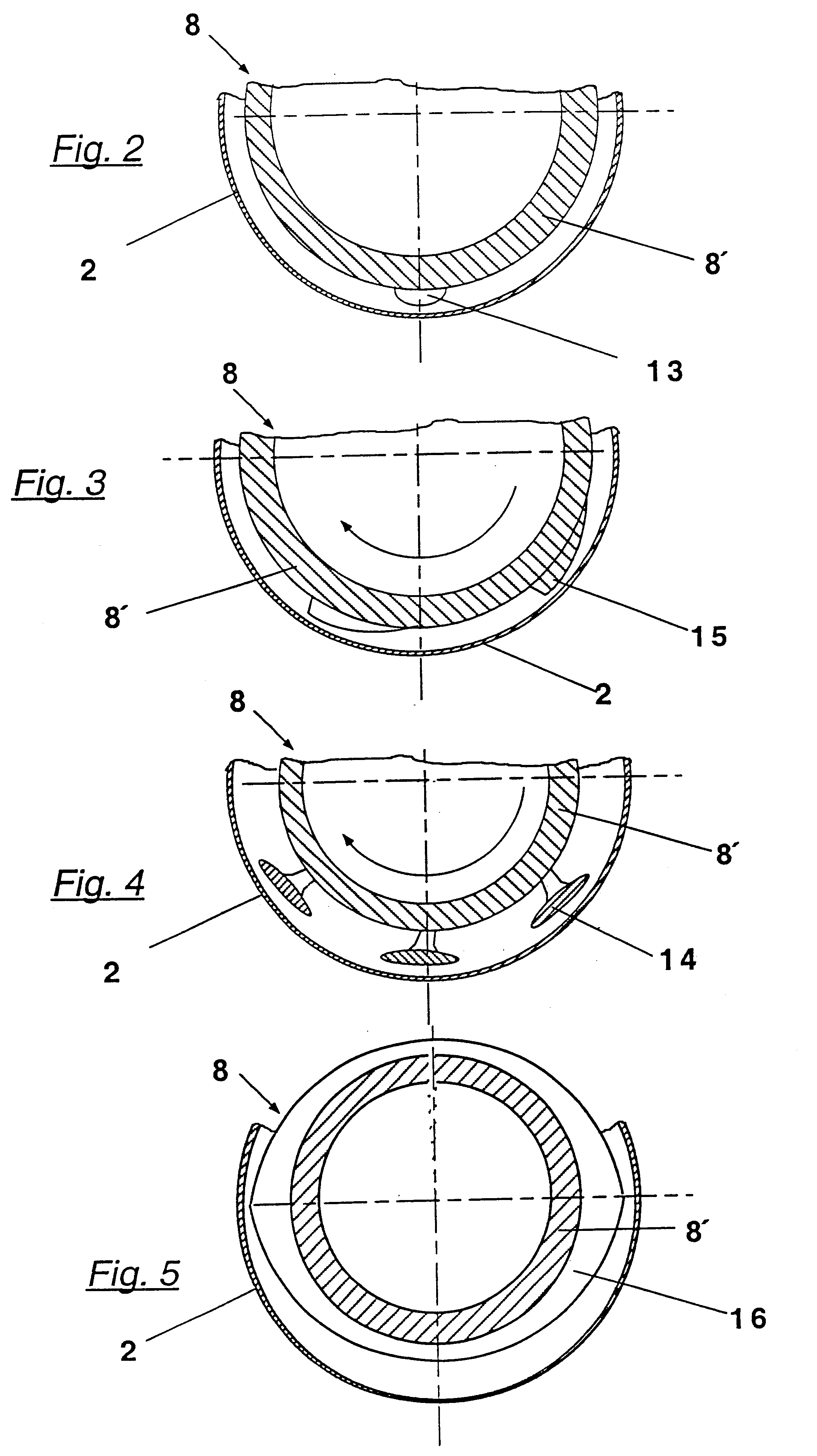
The invention uses various combinations of clearing elements in which distinctions can be drawn between several types of these clearing elements whose construction is fundamentally different. Thus, one type of clearing element is in the form of hydrodynamically effective blades around which the suspension flows. These can be moved relative to the suspension in the intermediate space between the rotor and the screen element. As a result of this design, pressure and suction phenomena specifically occurs which promotes throughput efficiency. Another type of clearing element utilizes mounted elevations which are essentially in the form of spherical segments or "bumps". These are disposed on a rotor body. Another clearing element design utilizes mounted elevations which have a more or less pronounced wedge shape. Still another clearing element design uses the rotor body itself which has a particular shape. This shape may have an oval configuration or may have the form or shape of a rounded polygon, e.g., a triangle or a lobed rotor.
With the rotor of the pressure screening apparatus according to the invention, the different clearing elements can be arranged such that the screen clearing effect in different clearing zones is increased during the course of the transport flow. Initially, the paper stock suspension is relatively thin immediately after entry into the pressure screening apparatus and has a high content of accepted stock and fillers. Thus, the demands on the screen clearing are lower at this point than during the later course. As a general rule, a decreased clearing effect serves to improve the grading quality, i.e., the separation efficiency. Thus, more fibers reach the accepted stock. In contrast, if too much of the accepted stock and fillers were to flow through the screen in this first zone, they would not be present as wet and support material in the subsequent grading zones. By utilizing the invention, the grading effect can be evened out so that a favorable mixture of fibers and accepted stock is present in larger areas of the screening apparatus. This is important for "saving" the long fibers, which would otherwise be too readily rejected permanently, i.e., would reach the reject outflow of the pressure screening apparatus.
The tendency to force substances through in the transport direction can also be increased with the invention. For example, the separation boundary between the rejected and accepted portions at a screen element can be shifted as the clearing effect increases. As a result, portions which are held back when the force-through tendency is weaker, are allowed to pass through when the tendency is stronger. In this connection, it is favorable for the clearing elements which have a high force-through tendency, e.g., those with wedge-shaped elevations or triangular contours, to be utilized only in a small area of the revolving screen. As a result, the achievable advantages greatly outweigh the disadvantages. Moreover, such configurations are themselves more particularly strong or robust when exposed to the flow forces. Moreover, such configurations, for their part, cause only a small load by alternate bending stresses at this particularly endangered point of the screen element. It may also be advisable to connect the increasing clearing effect with a falling force-through tendency, such as when too much dirt accumulates in the downstream clearing zones.
It can be advantageous for the screen clearer to have a modular construction. In such a design the screen clearer can utilize several parts or sections which are detachably coupled together, each of which e.g., forms a clearing zone. Thus, clearing zones can be combined in a suitable and interchangeable manner. Moreover, this design allows for matching the screening apparatus to a specific application, e.g., by changing the sequence of clearing zones. Additionally, this design allows the worn-out parts to be exchanged more easily.
It is also possible to combine the configuration of the screen clearer of the invention described above with a specific characteristic of the screen element. For example, a screen element can be provided with screen apertures that decrease in size continuously or stepwise in the direction of transport as described in DE 44 32 842, the disclosure of which is expressly incorporated by reference it its entirety. This design takes into account the dirt load which increases during the passage through the screening apparatus. Optimum grading quality, high throughput, and operating safety can be combined in this manner.
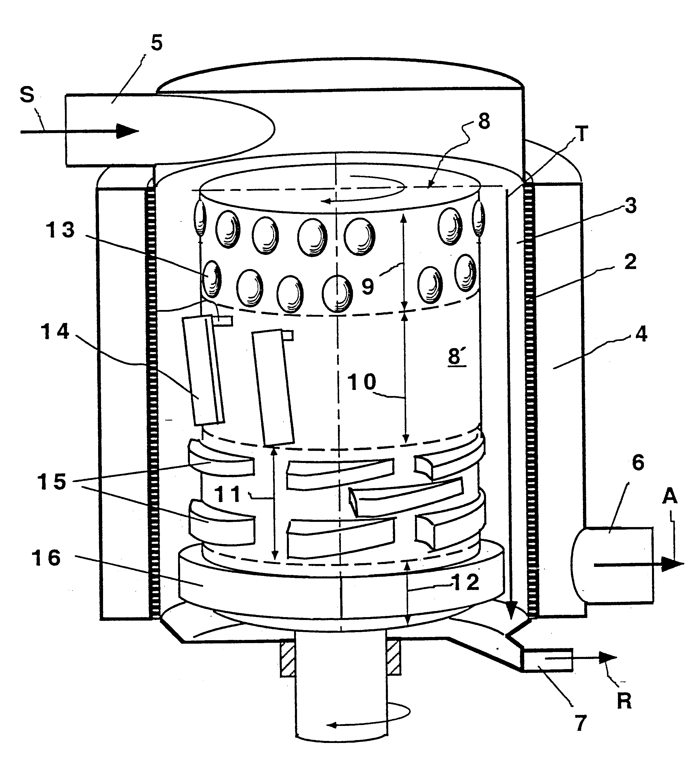
According to one aspect of the invention there is provided a pressure screening apparatus for screening a stock suspension including an inflow chamber, a suspension inflow connected to one end of the inflow chamber, a reject outflow connected to another end of the inflow chamber, an accepted stock chamber, an acceptance stock pipe connected to the accepted stock chamber, at least one screen element disposed between the inflow chamber and the accepted stock chamber, a screen clearer adapted to move with respect to the at least one screen element for preventing clogging of the at least one screen element, the screen clearer comprising at least a first clearing zone for producing a first clearing effect and at least a second clearing zone for producing a second clearing effect, the first clearing effect being different from the second clearing effect, wherein the stock suspension flows into the inflow chamber via the suspension inflow such that a portion of the stock suspension flows through the clearing zones and exits through the reject outflow. The at least one screen can separate the inflow chamber from the accepted stock chamber. The first clearing zone can include a plurality of elements and the second clearing zone can include a plurality of elements. The plurality of elements of the first clearing zone can have a shape which is different from the plurality of elements of the second clearing zone. The second clearing zone can produce a clearing effect which is greater than the first clearing zone. The second clearing zone can produce a greater flow resistance than the first clearing zone.

Problems solved by technology

This design causes part of the suspension which was rejected at the screen or part of the suspension which has already passed the screen as accepted stock, to be sucked back.
However, the ability of this design to efficiently screen the stock suspension is very limited.
However, the clearing effect of such depressions in this design is poor.
Moreover, such configurations, for their part, cause only a small load by alternate bending stresses at this particularly endangered point of the screen element.

Method used


Image

  • Pressure screening apparatus for screening a paper stock suspension and screen clearer for such a screening apparatus
  • Pressure screening apparatus for screening a paper stock suspension and screen clearer for such a screening apparatus
  • Pressure screening apparatus for screening a paper stock suspension and screen clearer for such a screening apparatus

Examples


Embodiment Construction

The particulars shown herein are by way of example and for purposes of illustrative discussion of the embodiments of the present invention only and are presented in the cause of providing what is believed to be the most useful and readily understood description of the principles and conceptual aspects of the present invention. In this regard, no attempt is made to show structural details of the present invention in more detail than is necessary for the fundamental understanding of the present invention, the description taken with the drawings making apparent to those skilled in the art how the several forms of the present invention may be embodied in practice.

FIG. 1 shows a pressure screening apparatus according to the invention having a screen element 2, here in the form of a revolving cylindrical screen, that divides the inner chamber of the pressure screening apparatus into an inflow chamber 3 and an accepted stock chamber 4. Stock suspension S can be fed into inflow chamber 3 vi...


PUM

PropertyMeasurementUnit
Forceaaaaaaaaaa
Flow rateaaaaaaaaaa
Diameteraaaaaaaaaa

Abstract

A pressure screening apparatus for screening a stock suspension and screen clearer for a pressure screening apparatus. The pressure screening apparatus includes an inflow chamber, a suspension inflow connected to one end of the inflow chamber, a reject outflow connected to another end of the inflow chamber, an accepted stock chamber, an acceptance stock pipe connected to the accepted stock chamber, at least one screen element disposed between the inflow chamber and the accepted stock chamber, a screen clearer adapted to move with respect to the at least one screen element for preventing clogging of the at least one screen element, the screen clearer comprising at least a first clearing zone and at least a second clearing zone, the first clearing zone having a plurality of clearing elements and the second clearing zone having a plurality of clearing elements which are different from those of the first clearing zone, wherein the stock suspension flows into the pressure screening apparatus via the suspension inflow such that a portion of the stock suspension flows through the clearing zones and exits the pressure screening apparatus through the reject outflow. The screen clearer includes a substantially cylindrical body having a cylindrical outer surface. The cylindrical outer surface includes at least a first clearing zone and at least a second clearing zone. The first clearing zone has a plurality of clearing elements. The second clearing zone has a plurality of clearing elements which are different from those of the first clearing zone. The cylindrical body is rotatably mountable.

Description

1. Field of the InventionThe invention relates to a pressure screening apparatus for screening a stock suspension and to a screen clearer.2. Discussion of Background InformationPressure screening apparatuses are typically used in treating paper stock suspensions, in order to process the stock suspension in a wet screening. For this purpose, the pressure screening apparatus contains a screen element which includes a number of apertures. The fibers contained in the suspension are allowed to pass through these apertures, while the undesired solid components of the suspension are prevented from doing so and are rejected and conducted out of the screening apparatus. This device may also be use for separating various grades of fiber components, i.e., separating the shorter fibers from longer fibers. Such screening apparatuses typically use round holes or slits as the grading apertures. In most cases, pressure screening apparatuses of the type under consideration here also utilize screen c...

Claims


Application Information

Patent Timeline
IPC IPC(8): D21D5/02D21D5/00
CPCD21D5/026
Inventor FRIEDRICH, HANSBRUCKNER, JOSEFVEH, GERHARD
Owner VOITH SULZER PAPIERTECHN PATENT
Why Eureka
Try Eureka