
Apparatus for providing video resolution compensation when converting one video source to another video source

a technology of video resolution compensation and video source, applied in the field of video processing, can solve the problems of jerky motion, poor image obtained with a conversion from analog to digital, and different resolution between analog signal and video display monitor

Inactive Publication Date: 2001-09-25
HEWLETT PACKARD DEV CO LP
View PDF17 Cites 36 Cited by
  • Summary
  • Abstract
  • Description
  • Claims
  • Application Information

AI Technical Summary

Problems solved by technology

One problem with analog signals is that typically they are in an interlaced format, meaning that half the screen lines, for example, the odd lines, are scanned first and then the remaining half of the scan lines, typically the even lines, are scanned second in such a fashion so that the two screens are interlaced together in order to enhance resolution.
This is a problem since most computer video monitors are progressive scan, which results in better resolution.
When analog images are converted field by field, since each field has only half the information that is otherwise required for display, a very poor, if not unacceptable, image is obtained with a conversion from analog to digital.
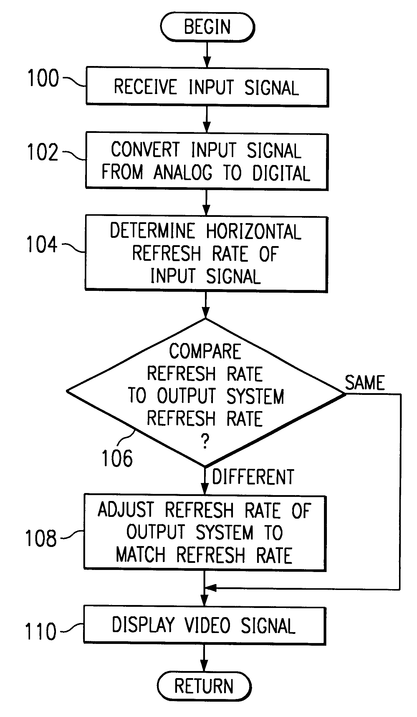
Converting from one refresh rate to the other refresh rate may result in field dropping or repetition which results in jerky motion.
Another problem is that the resolution is different between the analog signal and the video display monitor.

Method used


Image

  • Apparatus for providing video resolution compensation when converting one video source to another video source
  • Apparatus for providing video resolution compensation when converting one video source to another video source
  • Apparatus for providing video resolution compensation when converting one video source to another video source

Examples


Embodiment Construction

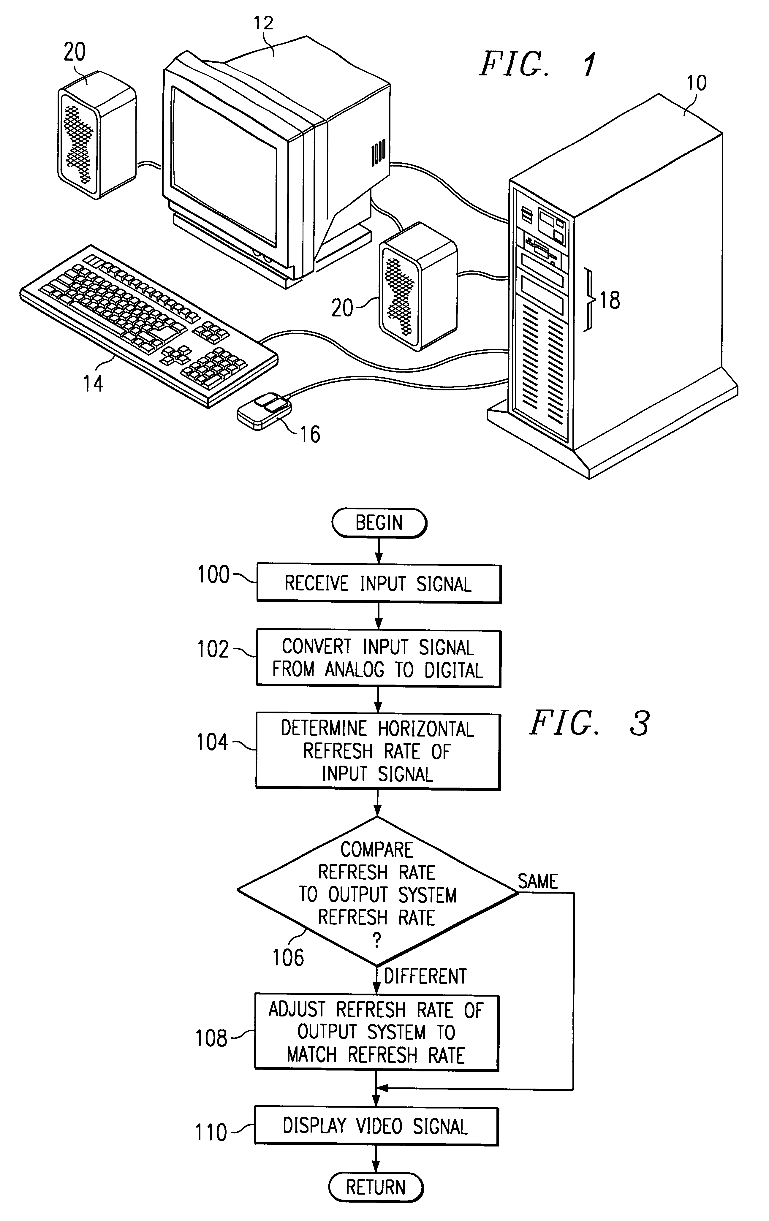
Illustrated now in FIG. 1 is a computer system 10 according to the present invention. Computer 10 includes multimedia features and devices and includes a video monitor display 12, a keyboard 14, a pointing device such as mouse 16, disk storage device 18, and audio speakers 20. Disk storage device 18 may be any type of disk storage technology such as a floppy disk drive, a hard disk drive, or compact disc readable memory drive, or other type writeable or erasable storage devices typically known to those skilled in the art. Keyboard 14 provides data input for the user, as does pointing device 16. Additionally, video display 12 is typically a progressive scan, multi-sync monitor, but may also be able to display interlaced scanned imaging.

Within computer 10 there are other various devices for operation. These devices include a central processing unit, such as those typically provided by the Intel Corporation, such as the Pentium microprocessor, or the PowerPC microprocessor manufactured...


PUM


Abstract

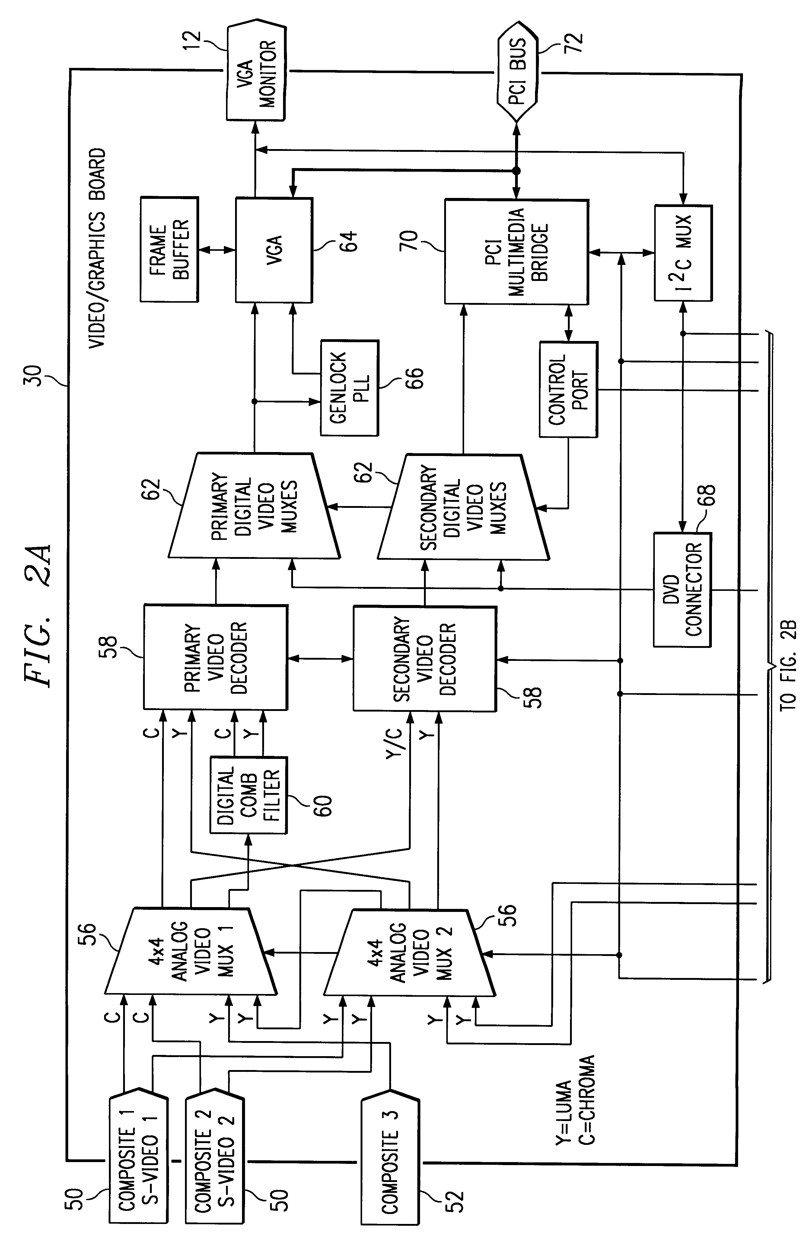
An apparatus and system for providing video processing is disclosed. Within the system and the apparatus there is an analog video signal input means, which is connected to a video signal output means, which are both coupled to a video resolution compensation means. The analog video signal input means provides decoding of a first signal type received by the input means. The first signal type operates at a first refresh rate. The video signal output means receives the decoded first signal type and converts the decoded first signal type into a second signal type, which has a second refresh rate. This second signal type typically is compatible for viewing on a display incompatible with the first signal type. Then, the video resolution compensation means modifies the second refresh rate associated with the decoded second signal type so as to be compatible with the first refresh rate and displayable on the video monitor.

Description

1. The Field of the InventionThe present invention relates generally to video processing in a computer system and, more particularly, to converting a video signal to another type of video signal for display in a computer system. More particularly still, the present invention relates to a video processing system that provides resolution enhancement of a signal being converted from one standard to a second standard to be displayed on the computer system.2. Prior ArtPersonal computer systems are becoming much more versatile in their functionality and utilization. Most personal computers now include multimedia capabilities, such as being able to handle either video or audio input and output functions, or both. In handling selected video input sources, a typical computer normally operates in a digital mode and requires the input source material to be in digital form. The computer system, otherwise, must be able to convert non-digital information into digital information for further proce...

Claims


Application Information

Patent Timeline
IPC IPC(8): H04N7/01
CPCH04N7/0105
Inventor VOLTZ, CHRISTOPHERBARKER, JOHN C.
Owner HEWLETT PACKARD DEV CO LP
Learn More