
Fluid and elastomer apparatus

a technology of fluid and elastomer, applied in the direction of machine supports, shock absorbers, springs/dampers functional characteristics, etc., can solve the problems of insufficient fluid mass in the straight-through inertia track, lack of halwes tuneability, and insufficient fluid mass

Inactive Publication Date: 2001-09-25
LORD CORP
View PDF32 Cites 26 Cited by
  • Summary
  • Abstract
  • Description
  • Claims
  • Application Information

AI Technical Summary

Problems solved by technology

Notably, Halwes suffers from the problem that it cannot adequately compensate for temperature differentials which cause expansion of the fluid therein.
Further, it may be difficult to obtain enough fluid mass in the straight-through inertia track design as described in Halwes.
Further, there is a lack of tuneability in Halwes.
Furthermore, the pockets formed in elastomer to receive lugs 34 in Halwes may act as stress concentrators which may adversely effect rubber fatigue.

Method used


Image

  • Fluid and elastomer apparatus
  • Fluid and elastomer apparatus
  • Fluid and elastomer apparatus

Examples


Embodiment Construction

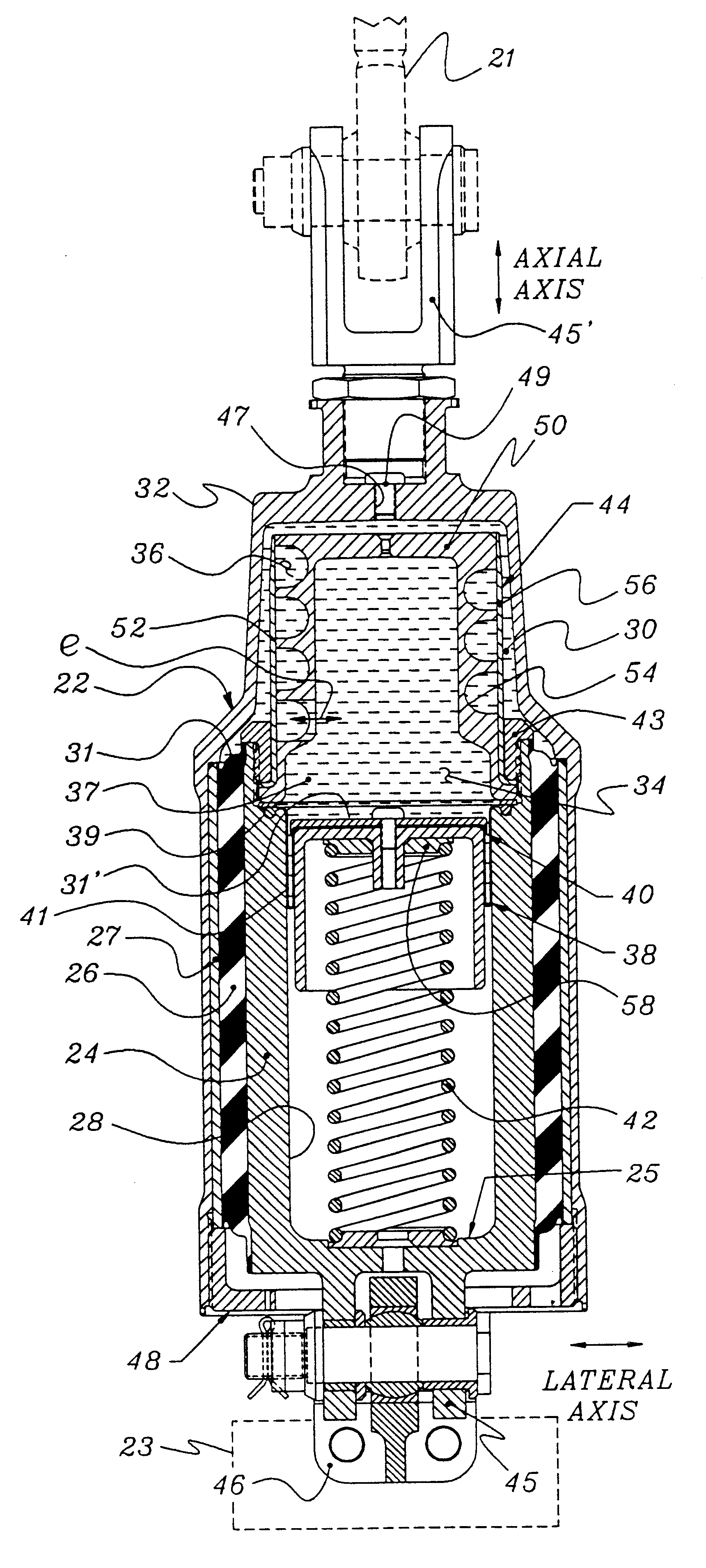
The following parameters are representative of a test isolator apparatus of FIG. 3d in accordance with the present invention which was manufactured and tested in the assignee's laboratory. The values herein are exemplary, and not to be considered limiting.

Kaxial dynamic of elastomer 26 = 5,500 lb. / in.

Fluid 37 = Perfluorinated polyether

Elastomer 26 = Natural rubber and polybutadiene blend

Axial stiffness of coil spring 42 = 70-150 lb. / in.

Length of coil 42 = about 5.0 in. installed

Prepressure in chambers 30, 34 = about 50 psi

Length of inertia track 36 = 3.0 in.

Area of inertia track 36 = 0.10 in..sup.2

Volume Stiffness (upper chamber 30) = about 2,000 psi / in..sup.3

Piston Area (upper chamber 30 ) = 2.7 in..sup.2

Piston Area (lower chamber 34 ) = 1.5 in..sup.2

FIG. 4 illustrates an experimental performance curve for the mockup of the present invention shown in FIG. 3d that was actually tested. Shown is a frequency sweep of dynamic complex stiffness K* (from about 700-5,500 lb. / in.) as a fun...


PUM


Abstract

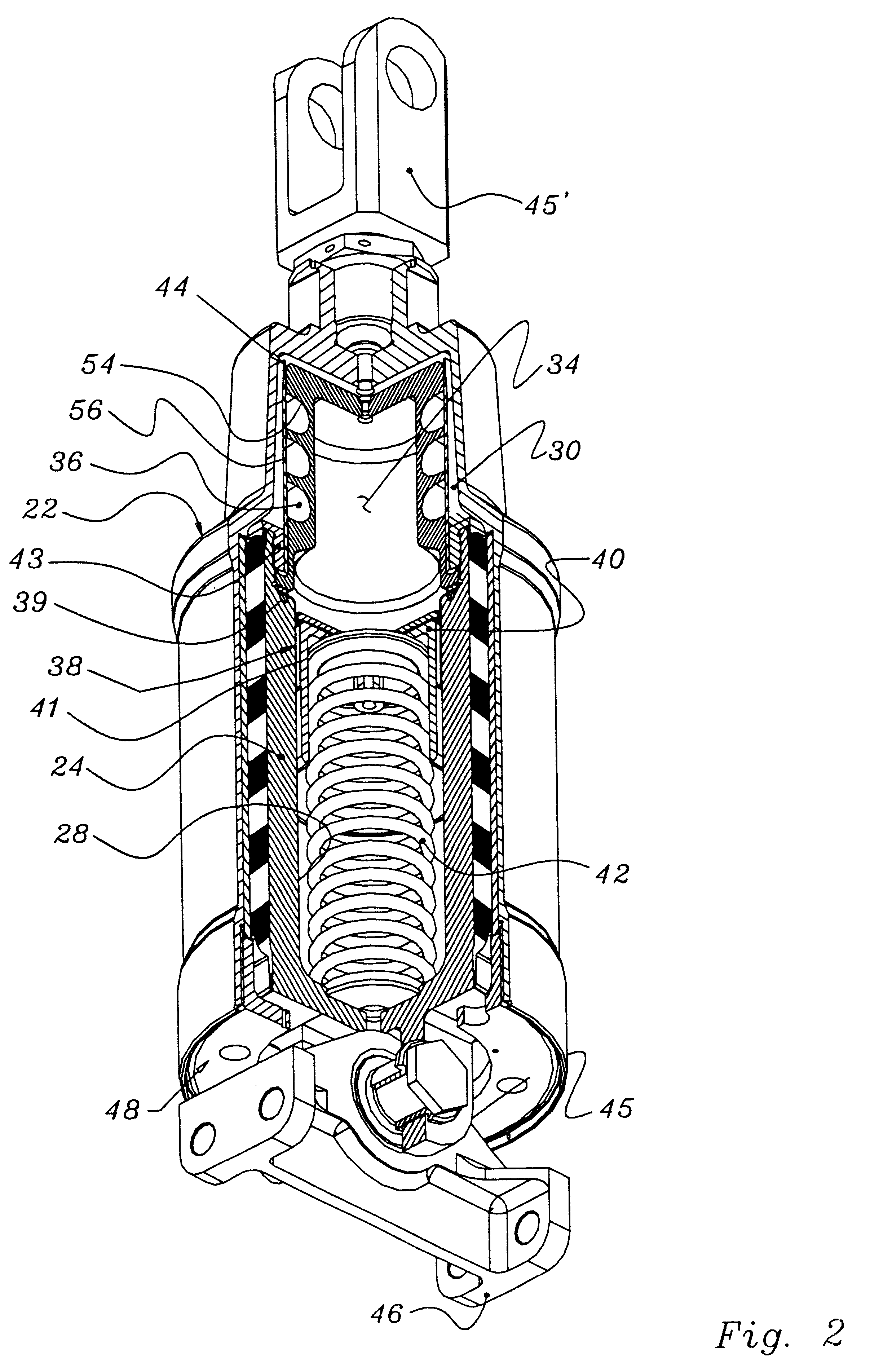
A fluid isolator apparatus (20) for isolating vibration between a vibrating member, such as a helicopter transmission or pylon and another structure, such as a helicopter fuselage. In one aspect, the fluid and elastomer apparatus (20) includes an inner member (24), an outer member (22), and an elastomer element (26) flexibly interconnecting them. First (30) and second (34) operating chambers are interconnected by a passageway (36). Fluid (37) oscillates between the operating chambers (32, 34) through passageway (36). A spring (42) flexibly suspends the piston (40) such that dynamic motion between said inner and outer member (24, 22) displaces piston (40) and spring (42). Preferably the a hollow cavity (28) houses both the piston (40) and a metal coil spring (42). The stiffness of the coil spring (42) may be interchanged to adjust a resonant parameter. Optionally, the piston mass itself or an additional tuning mass (58) mounted on the piston (40) may be used to accomplish tuning. Embodiments describing pistons (40) including rolling diaphragms, elastomer tubeforms, and metal bellows are described.

Description

This invention relates to devices for controlling dynamic vibration. Specifically, it relates to elastomer and fluid containing apparatus for control of vibration between a member and structure.Fluid and elastomer apparatus, i.e., hydraulic mountings, isolators, and dampers include a fluid which augments the isolation and / or damping characteristics that may be achieved within elastomer mountings alone. This augmentation may take the form of adding additional tuned damping or tuned inertial effects. Fluid mountings are generally described in LORD.RTM. Technical Article LL-2166 entitled "Understanding Hydraulic Mounts for Improved Vehicle Noise, Vibration and Ride Qualities" by W. C. Flower. Commonly assigned U.S. Pat. No. 4,811,919 to Jones describes an inertial-type fluid mounting which incorporates a volume compensator.Other examples of elastomer and fluid apparatus may be found in commonly assigned U.S. Pat. Nos. 5,540,549 and 5,501,434 to McGuire, 5,413,320 to Herbst, 5,374,039 t...

Claims


Application Information

Patent Timeline
Patent Type & Authority Patents(United States)
IPC IPC(8): F16F13/04F16F13/08F16F7/10
CPCF16F7/10F16F13/08F16F2228/00F16F2230/0047
Inventor MCGUIRE, DENNIS P.
Owner LORD CORP
Learn More