
Fluorescent X-ray analyzer useable as wavelength dispersive type and energy dispersive type

a fluorescent x-ray analyzer and wavelength dispersive technology, applied in the direction of material analysis using wave/particle radiation, material analysis by measuring secondary emission, instruments, etc., can solve the problems of inability to accurately compensate, complicated correlation between x-ray intensities and angle of emergence,

Inactive Publication Date: 2001-09-18
RIGAKU CORP
View PDF2 Cites 54 Cited by
  • Summary
  • Abstract
  • Description
  • Claims
  • Application Information

AI Technical Summary

Problems solved by technology

On the other hand, in the X-ray analysis, the intensity of X-rays to be measured depends on the angle of emergence and the correlation therebetween is complicated.
Moreover, even though compensation for the difference in angle of emergence is made, the correlation between the X-ray intensities with respect to the angle of emergence depends also on the composition of the sample and is thus complicated.
Therefore, the compensation cannot be made accurately and, because of this uncertainty, the analyzing accuracy cannot be increased.
Accordingly, during detection by the use of the energy dispersive type detector, the sensitivity tends to lower and, particularly where the fluorescent X-rays emitted from a minute area of the sample are desired to be detected, no sufficient sensitivity required for the analysis cannot be secured.
Also, the conventional fluorescent X-ray analyzing apparatus that can be used as the wavelength dispersive type and the wavelength dispersive type one at a time has the following problem.
As hereinabove discussed, according to the prior art, the fluorescent X-ray analyzing apparatus that can be used as either a wavelength dispersive type or an energy dispersive type is incapable of performing a quick and accurate analysis.

Method used


Image

  • Fluorescent X-ray analyzer useable as wavelength dispersive type and energy dispersive type
  • Fluorescent X-ray analyzer useable as wavelength dispersive type and energy dispersive type
  • Fluorescent X-ray analyzer useable as wavelength dispersive type and energy dispersive type

Examples


second embodiment

the present invention will now be described.

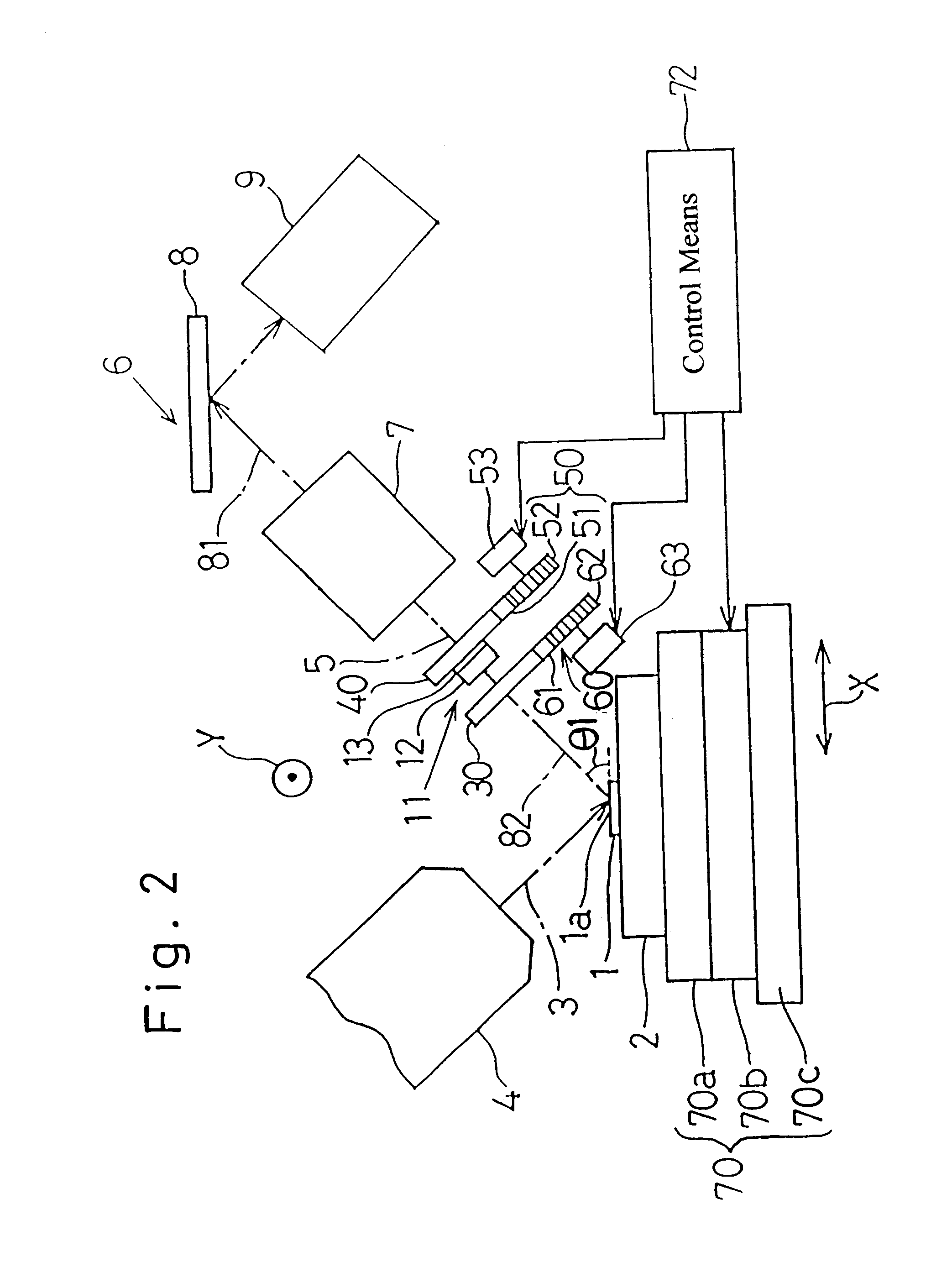
As shown in FIG. 2, as is the case with the analyzing apparatus according to the foregoing embodiment, the analyzing apparatus shown therein comprises a sample support 2 on which a sample 1 is placed, an X-ray source 4, and a wavelength dispersive type detecting means 6 including a divergent Soller slit 7, a spectroscope 8 and a first detector 9. A plate-shaped first collimator 30 is disposed on the path 81 of travel of the fluorescent X-ray between the sample 1 and the detecting means 6. As shown in FIG. 3, the first collimator 30 has a plurality of, for example, three throttling apertures 31a, 31b and 31c of different diameters defined therein in a row. The first collimator 30 may not be always limited to that of a plate-like shape, but may be of any suitable shape, for example, having an upper wall or a stepped wall adjacent the sample for improving the S / N ratio of the fluorescent X-ray generated from the sample, such as disclosed in t...


PUM


Abstract

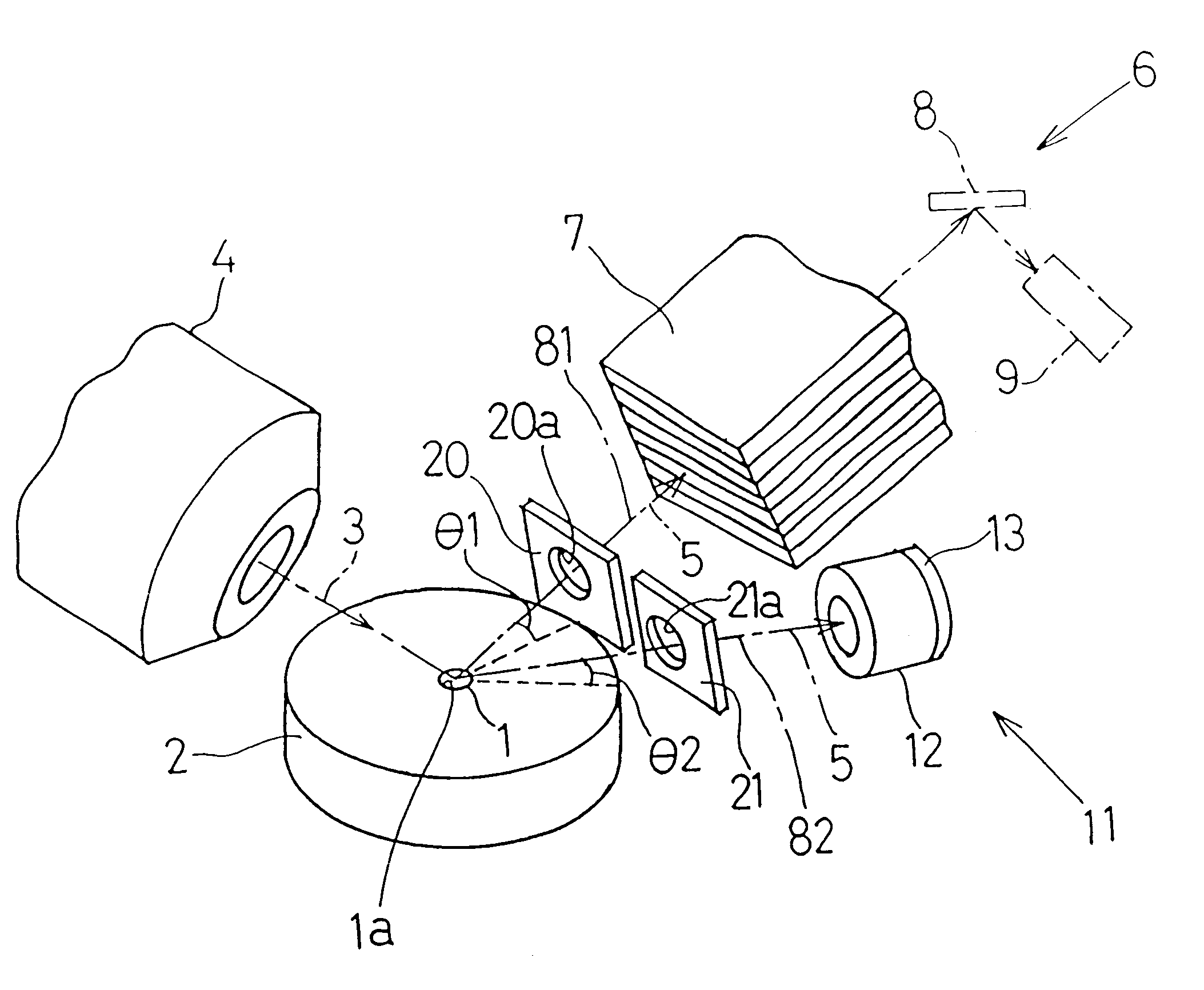
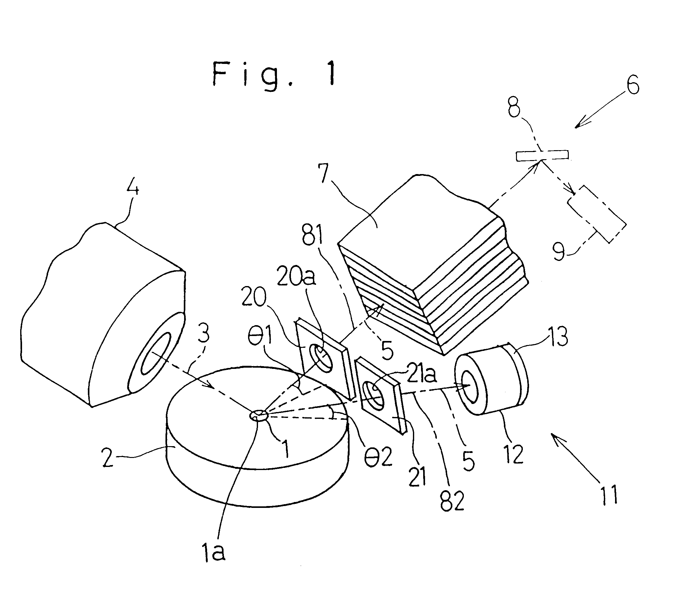
A fluorescent X-ray analyzing apparatus capable of being used as either a wavelength dispersive type or an energy dispersive type is provided, with which the analysis can be performed quickly and accurately. The fluorescent X-ray analyzing apparatus includes a detecting unit for detecting and analyzing fluorescent X-ray (5) emitted from at least one target area (1a) of a sample (1) to be analyzed as a result of excitation of such target area (1a) with a primary X-ray (3). The detecting unit includes a wavelength dispersive type detecting unit (6) including a spectroscope (8) and a first detector (9), and an energy dispersive type detecting unit (11) including a second detector (12) of an energy dispersive type. The angle theta1 formed between a first path (81) of travel of the fluorescent X-ray from the target area (1a) towards the spectroscope (8) and a surface of the sample (1) is equal to the angle theta2 formed between a second path (82) of travel of the fluorescent X-ray from the target area (1a) towards the second detector (12) of the energy dispersive type and a surface of the sample (1), but the second path (82) is shorter than the first path (81).

Description

1. Field of the InventionThe present invention generally relates to a fluorescent X-ray analyzing apparatus and, more particularly, to the fluorescent X-ray analyzing apparatus capable of being used selectively as a wavelength dispersive type and an energy dispersive type.2. Description of the Prior ArtThe fluorescent X-ray analyzing apparatus is well known as an instrument for analyzing elements contained in an area of interest of a sample by applying primary X-rays to such area interest to excite the target area and subsequently detecting, by means of a detecting means, fluorescent X-rays emitted from the area of interest as a result of excitation thereof. The detecting means are currently available in two types; wavelength dispersive type and energy dispersive type. The area of interest of the sample referred to hereinabove and hereinafter is intended to encompass at least a portion of a surface of the sample at an arbitrary site on the sample and its nearby deep structure. At le...

Claims


Application Information

Patent Timeline
IPC IPC(8): G01N23/223G01N23/22
CPCG01N23/223G01N2223/076
Inventor KAWAHARA, NAOKISHOJI, TAKASHIMISONOO, TAKASHIAOYAGI, KOUICHIARAKE, AKIRASAKAMOTO, TAKASHIINOUE, MINORUYAMADA, YASUJIRO
Owner RIGAKU CORP
Learn More