Process and device for inflating a tire

a tire and tire technology, applied in the direction of wheel mounting apparatus, instruments, static/dynamic balance measurement, etc., can solve the problem of not being able to inflate a tire mounted on a rim

Inactive Publication Date: 2001-09-11
MICHELIN RECH & TECH SA
View PDF4 Cites 5 Cited by
  • Summary
  • Abstract
  • Description
  • Claims
  • Application Information

AI Technical Summary

Problems solved by technology

One major disadvantage of these known inflation devices is that they are not suitable for inflating a tire mounted on a rim, such as the special rim described in the aforementioned U.S. Pat. No. 5,836,366, because, once said first bead of the tire has been mounted on said first seat of this special rim, the axially inner flange of this first seat and the aforementioned inclination of the latter towards the outside would hinder the circumferential deformation of this first bead towards said second bead, for creating said annular space.

Method used


Image

  • Process and device for inflating a tire
  • Process and device for inflating a tire
  • Process and device for inflating a tire

Examples


Embodiment Construction

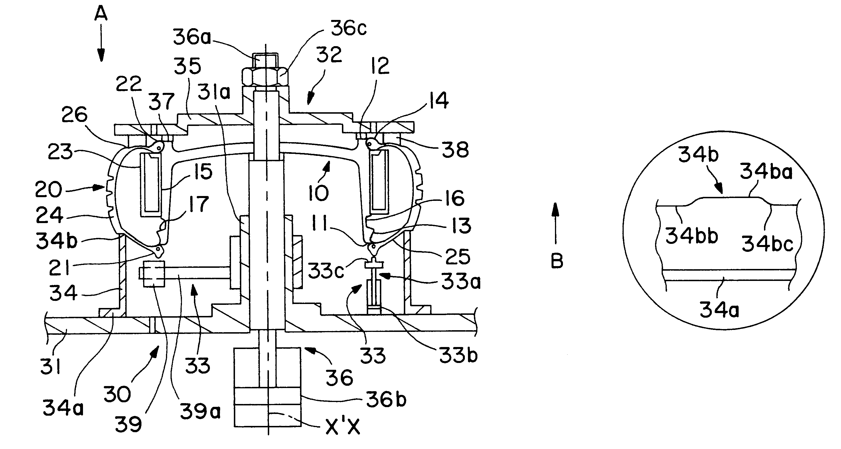
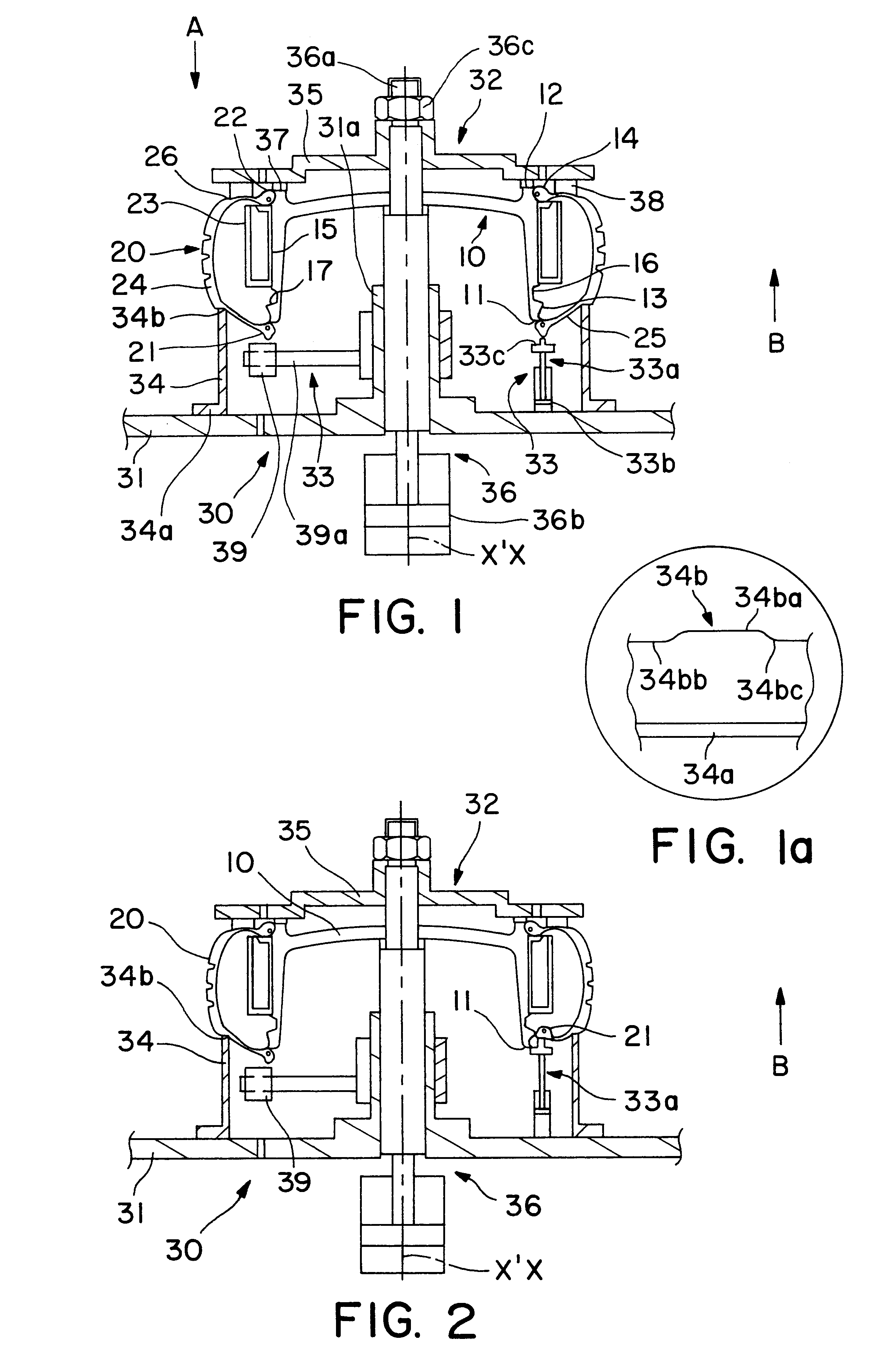
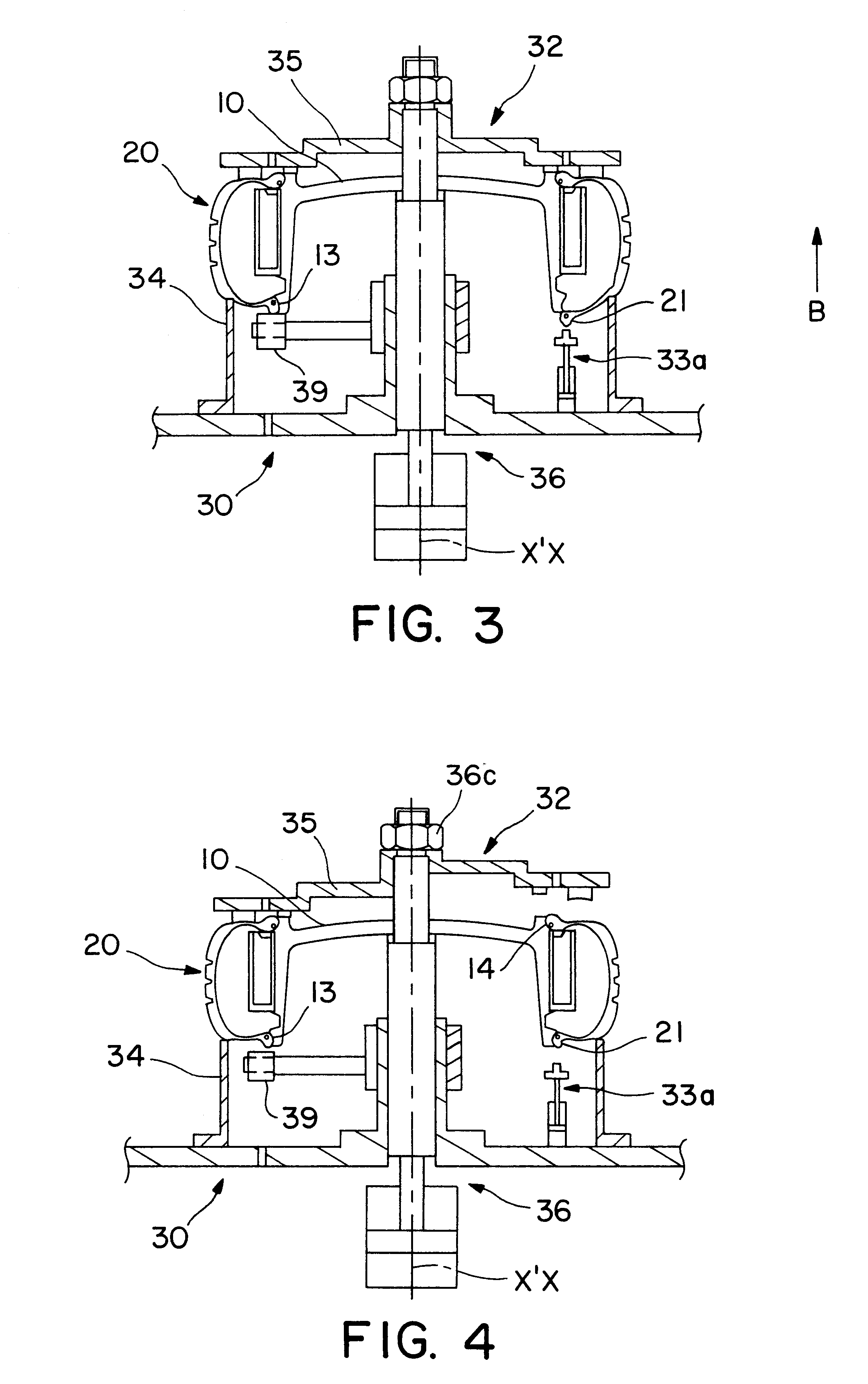
As can be seen in FIG. 1, an inflation device 30 according to the invention comprises a frame 31, a bell 32 which is mounted on the frame 31 and which is intended to cooperate with the tire 20 and the special rim 10, and means 33 which are mounted within the bell 32 and which are intended to cooperate with the first bead 21 of the tire 20.

The wall of the frame 31 is provided with an air inlet (not shown) which is connected hermetically to a compressed-air supply system.

In this example of embodiment, the bell 32 is formed of a fixed part 34 which is mounted on the frame 31 and a mobile part 35 which is provided to slide relative to the former by means of a control means 36.

These parts 34 and 35 are intended, respectively, to surround the sidewalls 25 and 26 of the casing 20 hermetically for the purpose of inflation thereof, when said tire is provided with said rim 10.

The fixed part 34 has a geometry of revolution, for example of cylindrical shape extended at a right-angle by a base 3...


PUM


Abstract

A process and device for inflating a tire by forming, within an enclosure in which there are enclosed the rim and the beads of the tire, an inflation orifice between a first seat of the rim and a first bead, then introducing compressed air into said orifice and closing it such that the tire is inflated and mounted hermetically on the rim. Before forming this orifice, the first bead of the tire is located axially to the outside of the first seat and the second bead is mounted hermetically on the second seat, then, to form the orifice, points on the first bead are pressed. The device for implementing the process includes a bell formed of a fixed part and a mobile part intended to slide relative thereto to tightly surround the tire on the rim for its inflation, and including, within the bell, a finger for pressing at points on said bead.

Description

BACKGROUND OF INVENTIONThe present invention relates to a process and device for inflating a tire. The invention applies to the inflation of a tire, the beads of which are respectively intended to be mounted on peripheral seats of a special rim, this inflation being effected without using the valve of said rim.The structure of this rim is described in detail in U.S. Pat. No. 5,836,366.As can be seen in FIG. 1, to which reference will be made hereafter, said rim 10 comprises, starting from its peripheral edges formed of two projections 11 and 12, a first and a second seat 13 and 14 inclined towards the outside and intended respectively to receive a first and a second bead 21 and 22 of the tire 20. Between the seats 13 and 14 there is provided, firstly, a bearing surface 15 intended to receive a bearing support 23 for the tread 24 and, secondly, a mounting groove 16 connecting the bearing surface 15 to an axially inner flange 17 of said first seat 13.In the Test of the present descrip...

Claims


Application Information

Patent Timeline
Patent Type & Authority Patents(United States)
IPC IPC(8): B60C25/00B60C25/14B60C23/10
CPCB60C25/145B60C25/00
Inventor SCHMITT, LUDOVIC
Owner MICHELIN RECH & TECH SA
Why Eureka
Try Eureka