
Method and apparatus for electroplating

a technology of electroplating and apparatus, applied in the direction of cell components, manufacturing tools, electric circuits, etc., can solve the problem that the geometry of the bus bar is difficult to implement in the actual rack, and achieve the effect of improving the thickness distribution of the plating and improving the electroplating

Inactive Publication Date: 2001-07-31
IBM CORP
View PDF6 Cites 30 Cited by
  • Summary
  • Abstract
  • Description
  • Claims
  • Application Information

AI Technical Summary

Problems solved by technology

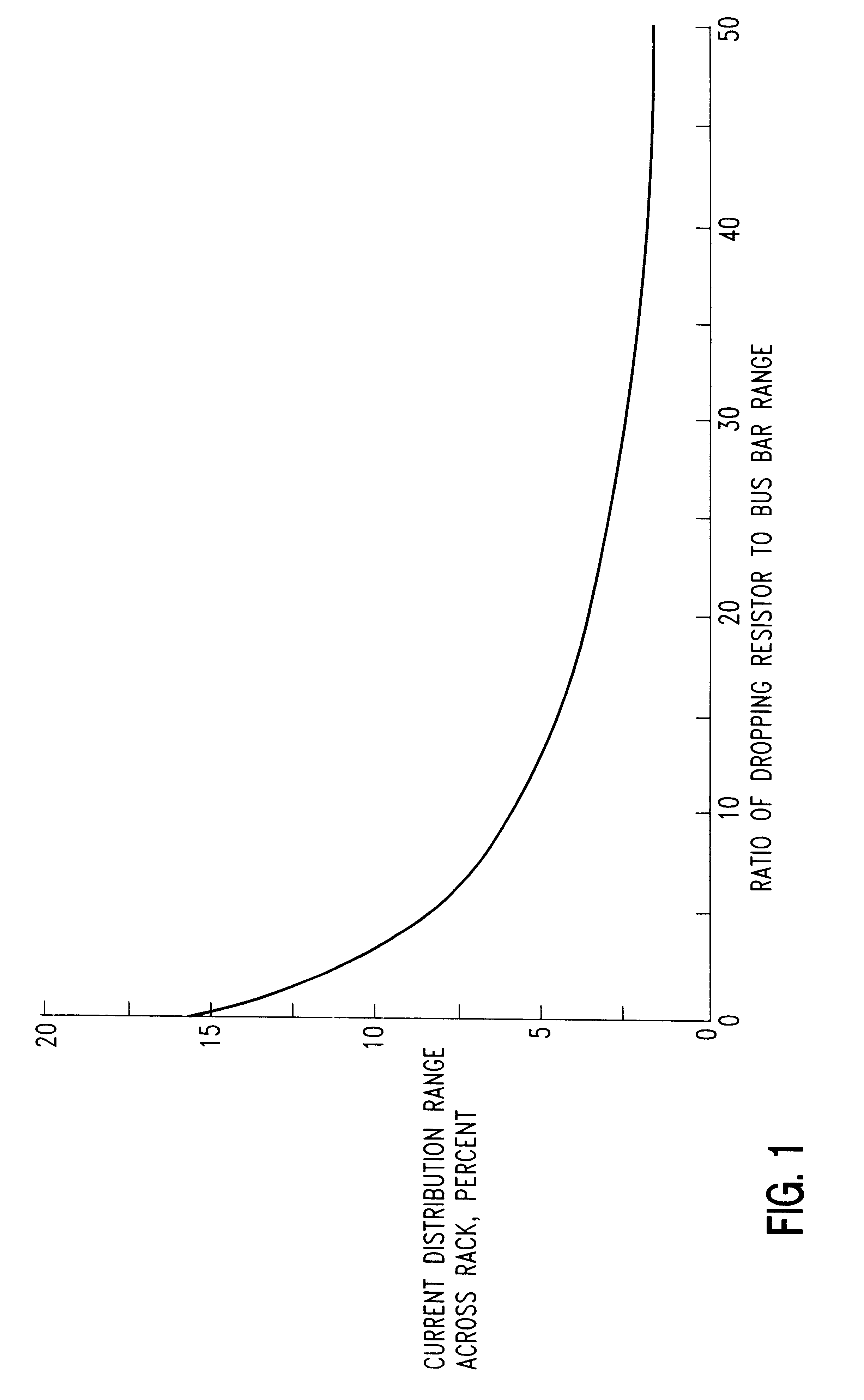
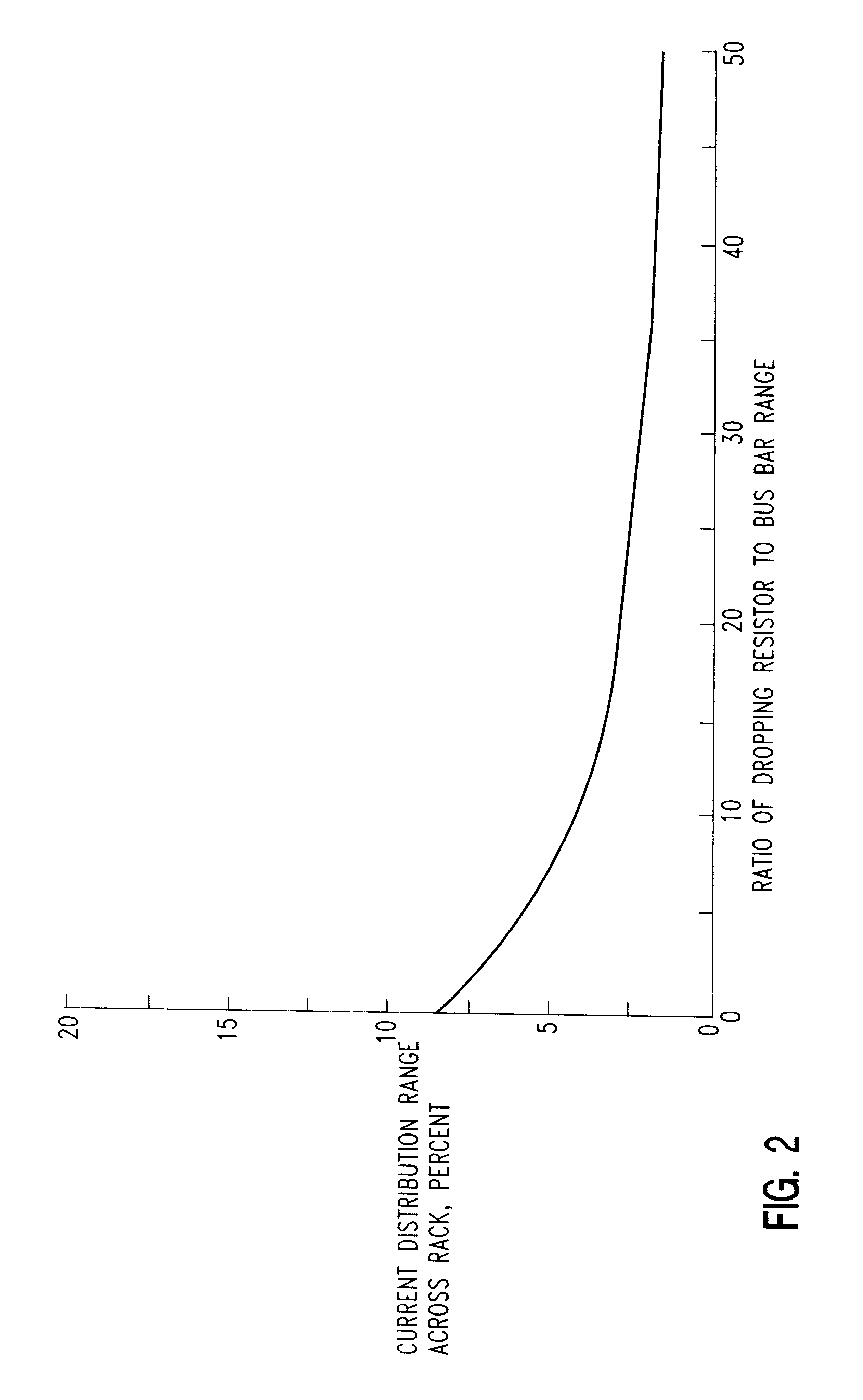
However, tailoring the bus bars' geometry is difficult to implement in an actual rack due to the extra bus bar mass that is needed in the lower current regions to reduce the voltage drop between contacts and the design complexity this generates.

Method used


Image

  • Method and apparatus for electroplating
  • Method and apparatus for electroplating
  • Method and apparatus for electroplating

Examples


Embodiment Construction

For a better understanding of the present invention, together with other and further objects, advantages and capabilities thereof, reference is made to the following disclosure and the appended claims in connection with the above-described drawings.

For illustrative purposes only, reference is made to the electroplating arrangement disclosed in U.S. patent application Ser. No. 09 / 178,084 filed Oct. 23, 1998, now Pat. No. 6,176,985, as modified pursuant to the present invention. The entire disclosure of U.S. Ser. No. 09 / 178,084 is incorporated herein by reference. However it being understood that other electroplating apparatus can be modified pursuant to the present invention.

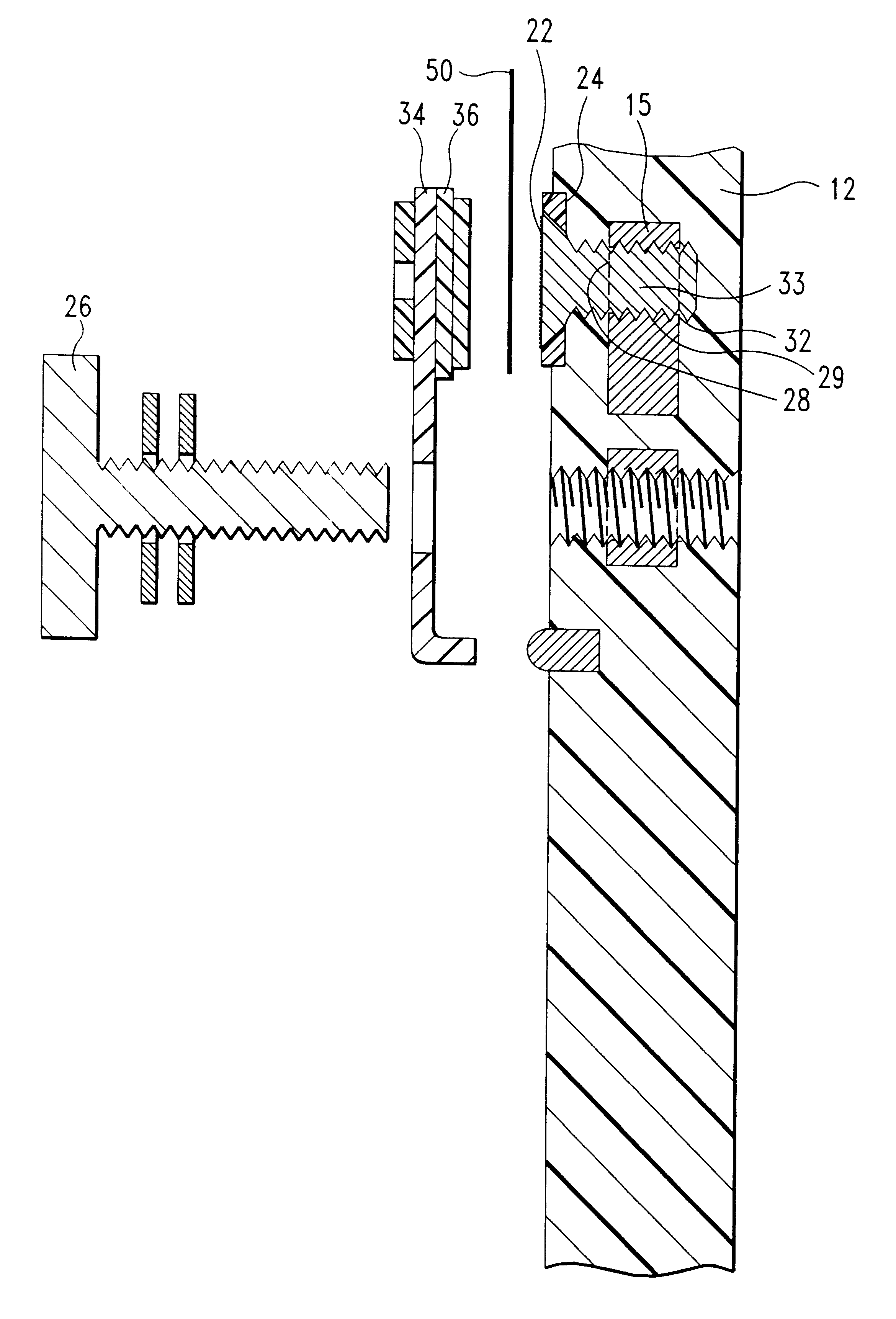
In FIG. 3 there is shown a supporting structure 10 having an electrically insulated surface 12 and an electrically conductive core 14 and 15 forming horizontal and vertical conductive members, respectively. The electrically conductive core 14 and 15 may be any electrically conductive material but is typically a m...


PUM

PropertyMeasurementUnit
resistivityaaaaaaaaaa

Abstract

Electrolytic plating of a workpiece is enhanced by providing a resistor between the workpiece and electrically conductive support member.

Description

DESCRIPTIONThe present invention relates to a method for enhancing the electroplating of an article and especially for electroplating of microelectronic and other precision components. The present invention is particularly concerned with improving the uniformity of plating thicknesses. Moreover, the present invention relates to electroplating apparatus capable of improving the uniformity of plating thicknesses.BACKGROUND OF INVENTIONElectrolytic plating is widely used for plating of microelectronic and other precision articles. For example, electroplating is widely practiced in the printed circuit industry to add layers of various metals to other conductors. Copper may be plated to increase the thickness of conductors. Layers of nickel and gold are routinely added to copper for protection to prevent oxidation. A great variety of materials, thicknesses and layers are known in the electroplating art.An important and major concern in electroplating is control of plated thickness distri...

Claims


Application Information

Patent Timeline
Patent Type & Authority Patents(United States)
IPC IPC(8): C25D21/12C25D17/06H05K3/24
CPCC25D17/06C25D21/12Y10S204/07H05K3/241
Inventor BRODSKY, WILLIAM LOUIS
Owner IBM CORP
Learn More