Rotary drill bit having filling opening for the installation of cylindrical bearings

a technology of cylindrical bearings and drilling bits, which is applied in the direction of cutting machines, shafts and bearings, mechanical equipment, etc., can solve the problems of substantial shortening the life of impairing the life of the actual radial bearing, and axial strain on the balls, so as to improve the axial improve the radial bearing arrangement of the rotary cutter bi

Inactive Publication Date: 2001-06-26
SANDVIK AB
View PDF6 Cites 43 Cited by
  • Summary
  • Abstract
  • Description
  • Claims
  • Application Information

AI Technical Summary

Benefits of technology

A primary object of the present invention is to provide a rotary drilling bit wherein the rotary cutter is axially secured by a flange on the rotary cutter without cutting into the bearing arrangement of the rotary cutter bit.
Another object of the present invention is to improve the radial bearing arrangement of the rotary cutter bit compared to rotary drilling bits of conventional design.
Still another object of the present invention is to improve the axial bearing arrangement of the rotary cutter bit compared to conventional rotary.

Problems solved by technology

These balls primarily do not have any bearing function but when the main axial bearings (e.g., Stellite.RTM. washers) become worn, the balls can be exposed to axial strains, which is not desirable since that can to a substantial degree shorten the life of the rotary cutter bit.
Also, there is a risk is that a difference in level may arise at transitions between the filler piece and the bearing race (i.e., there steps are formed between the filler piece and the bearing race if the filler piece is not positioned with exact precision), which naturally impairs the life of the actual radial bearing.

Method used


Image

  • Rotary drill bit having filling opening for the installation of cylindrical bearings
  • Rotary drill bit having filling opening for the installation of cylindrical bearings
  • Rotary drill bit having filling opening for the installation of cylindrical bearings

Examples


Embodiment Construction

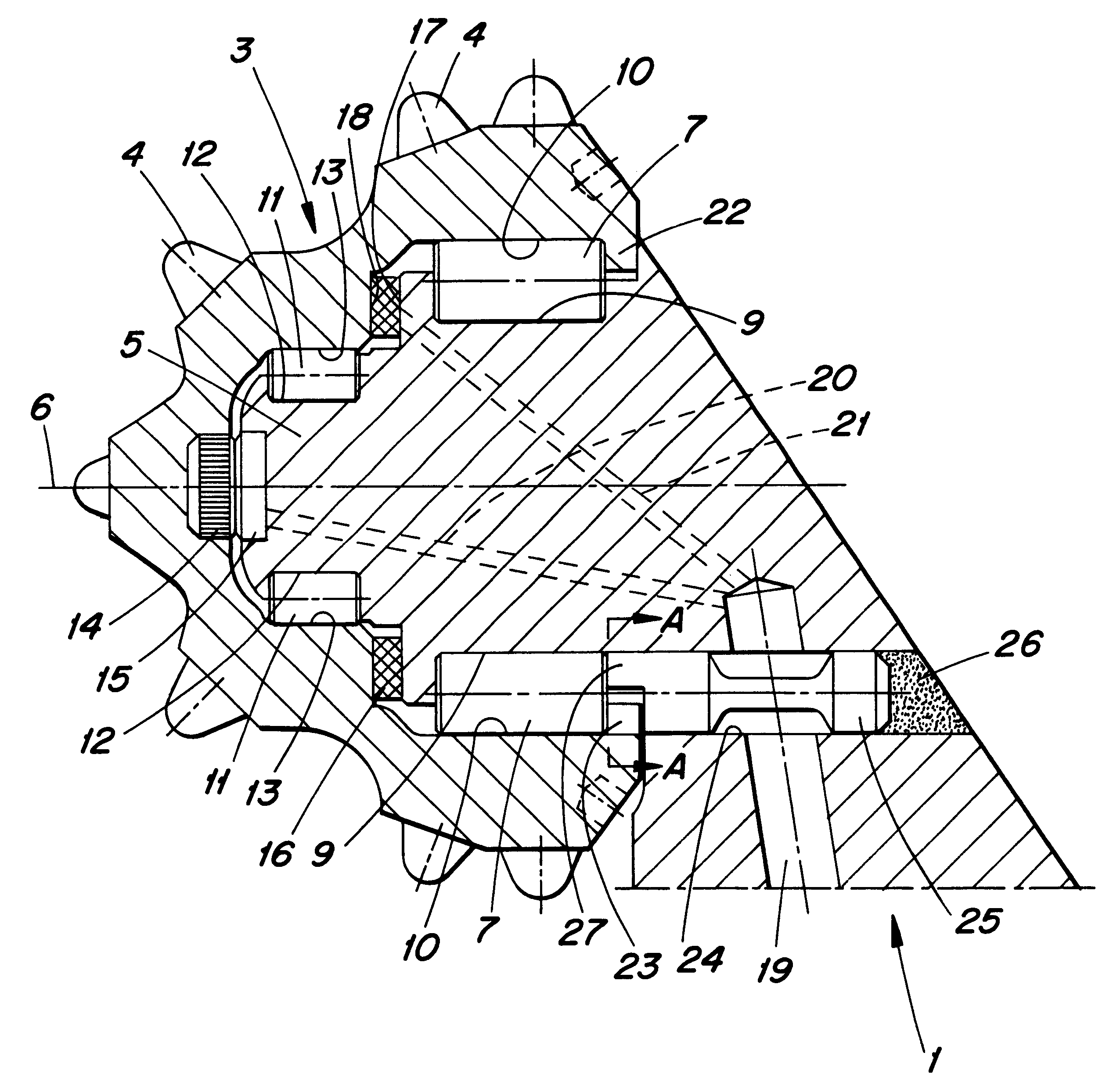
The rotary drilling bit shown in FIG. 1 is a so-called open rotary drilling bit, which usually is air-cooled. The rotary drilling bit comprises at least one leg 1 and at least one rotary cutter 3. A bearing journal 5 is formed integrally with the leg 1, and the rotary cutter 3 is mounted on the journal 5. In a usual manner the rotary cutter 3 has a number of rock cutting means, preferably in the shape of cemented carbide inserts 4. A number of bearing arrangements are formed between the rotary cutter 3 and the journal 5, and the rotary cutter 3 is symmetrical and rotatable relative to the journal 5 around an axis of rotation 6.

A radial base bearing or rear bearing is provided in connection with the open end of the rotary cutter 3, and said radial base bearing comprises an annular array of cylindrical first rolling elements 7, which cooperate partly with a radially inner first bearing race 9 disposed on the journal and partly with a radially outer second bearing race 10 disposed at t...


PUM


Abstract

A rotary drill bit includes a rotary cutter rotatably mounted on a leg. A radial bearing arrangement and an axial bearing arrangement are provided in an interface between the cutter and the leg. The leg includes a filling opening for enabling cylindrical rolling elements of the radial bearing arrangement to be installed. The cutter includes a radial flange which radially overlaps the radial bearing arrangement to secure the cutter on the leg. The flange, which is disposed axially behind the radial bearing arrangement and axially in front of the filling opening, includes a recess for accommodating the passage of the cylindrical rolling elements. A locking element is disposed in the filling opening for preventing dislodgement of the cylindrical rolling elements. The locking element includes a lip which projects axially forwardly of the radial bearing arrangement. The lip is disposed radially inwardly of the flange and terminates axially behind the radial bearing arrangement.

Description

TECHNICAL AREA OF THE INVENTIONThe present invention relates to a rotary drilling bit wherein a rotary cutter is mounted on a journal by means of cylinder bearings.PRIOR ARTA conventional manner to orient the rotary cutter of a rotary drilling bit in the axial direction relative to the journal of the leg is by inserting bearing balls in an interface between the cutter and the journal. The balls are introduced via a filling opening in the journal, whereafter said hole is closed by a locking pin which is welded to the journal. These balls primarily do not have any bearing function but when the main axial bearings (e.g., Stellite.RTM. washers) become worn, the balls can be exposed to axial strains, which is not desirable since that can to a substantial degree shorten the life of the rotary cutter bit.Through U.S. Pat. No. 4,256,193 there is previously known a rotary drilling bit which does not include a number of balls for axial locking of the rotary cutter relative to the journal of t...

Claims


Application Information

Patent Timeline
Patent Type & Authority Patents(United States)
IPC IPC(8): E21B10/08E21B10/22F16C43/06
CPCE21B10/22F16C43/06F16C2352/00
Inventor KARLSSON, LENNART
Owner SANDVIK AB
Why Eureka
Try Eureka