
Optical device with protective cover

a protective cover and optical device technology, applied in the field of optical discs, can solve the problems of resin substrates that are difficult to manufacture to uniform quality, adversely affect writing and reading performance, and are difficult to meet the requirements of uniform quality,

Inactive Publication Date: 2001-06-19
TDK CORPARATION
View PDF17 Cites 17 Cited by
  • Summary
  • Abstract
  • Description
  • Claims
  • Application Information

AI Technical Summary

Problems solved by technology

However, resin substrates are difficult to manufacture to uniform quality.
Especially when the resin substrates have a large diameter, they tend to be non-uniform, allowing birefringence and other factors to adversely affect writing and reading performance.
Additionally, the resin substrates are less resistant to heat and moisture and undergo deformation and deterioration in a hot humid atmosphere.
Also since resin substrates with a large diameter are less stiff, high-speed revolution at 1,800 rpm or higher, especially 3,000 rpm or higher causes axial runouts, resulting in a significant increase of focusing and tracking errors.
The glass substrates, however, are likely to fail, especially near their corner, upon receipt of impact as by accidental dropping or hitting.
Some optical discs are received in cartridges, but still can be broken as a result of vibration of the disc within the cartridge.
However, this structure cannot fully prevents a failure of the corner of the glass substrate when impact is applied thereto from an oblique direction.
This structure intends to prevent direct contact of the recording surface with the ambient atmosphere and reduce the weight, but not to prevent a failure of the glass substrate near its corner.
In fact, this optical information recording disc is less effective for preventing a failure of the glass substrate 2 near its periphery since the periphery of the glass substrate 2 is in close fit with the plastic holder frame 7.
Outside this range, a narrower space would be insufficient for shock absorption whereas the protective member rim spaced a greater distance would not be strong enough.
Outside this range, a narrower space would be insufficient for additional shock absorption whereas the protective member covering portion spaced a greater spacing would not be strong enough in this region.

Method used


Image

  • Optical device with protective cover
  • Optical device with protective cover
  • Optical device with protective cover

Examples


example 1

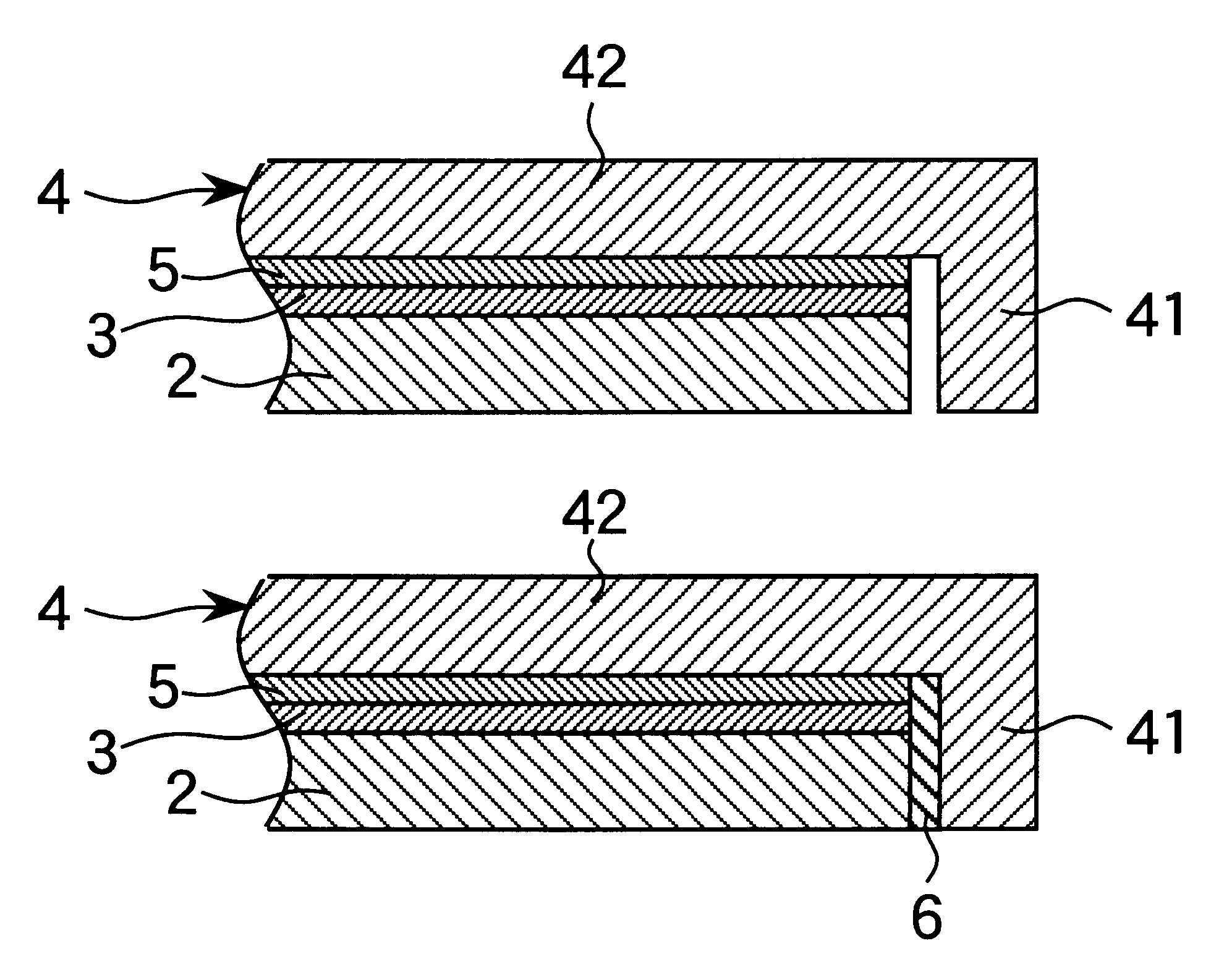
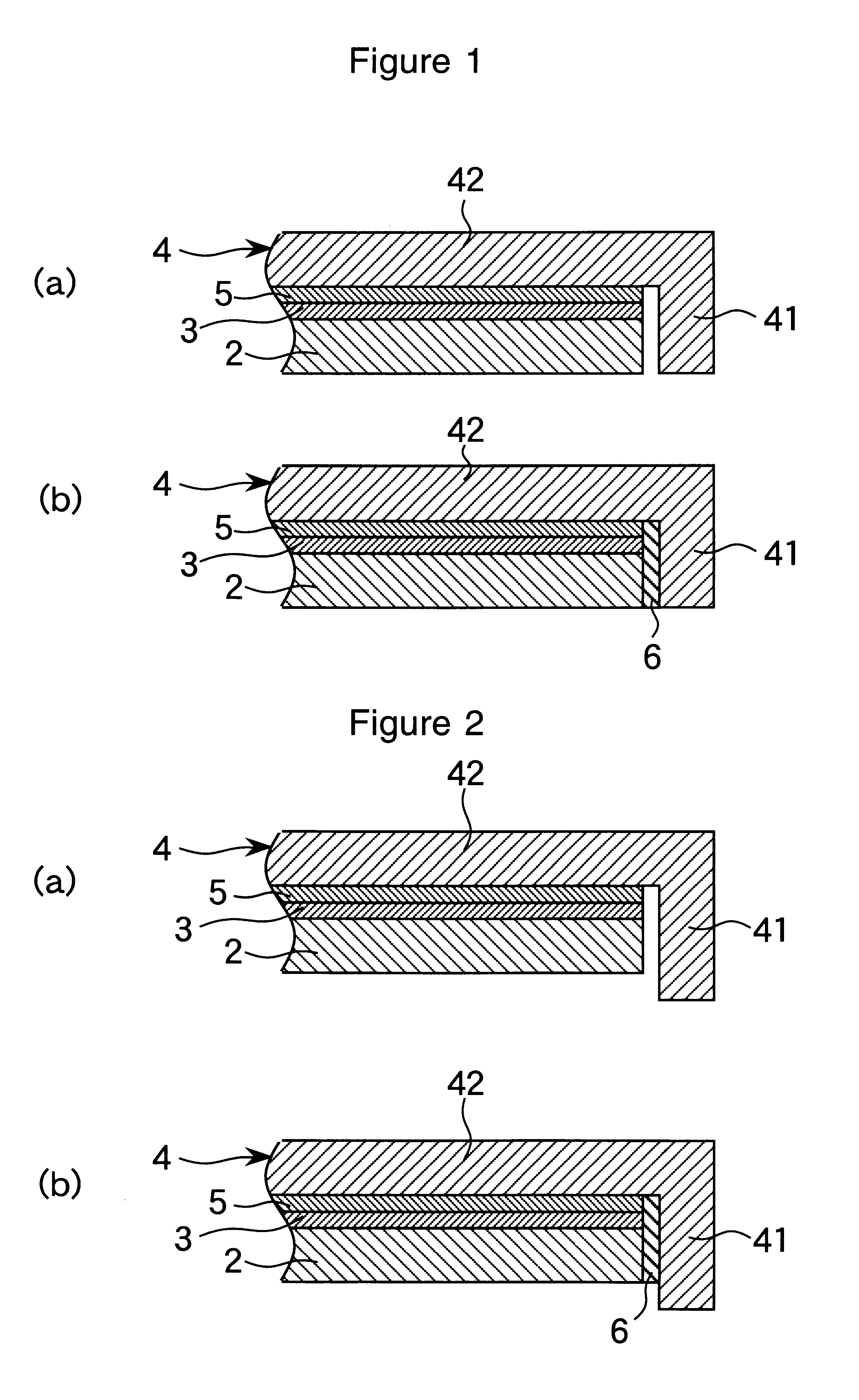
A magneto-optical disc sample of the structure shown in FIG. 1(b) was fabricated by furnishing a glass substrate 2 of chemically strengthened glass having an outer diameter of 200 mm and a gage of 1.2 mm. A layer of UV-cured acrylic resin, an intermediate layer of SiNx, a recording layer of TbFeCo, a protective layer of SiNx, a reflecting layer of aluminum, and a protective coat of UV-cured acrylic resin were successively formed on the glass substrate 2 to provide an information-carrying means 3. The information-carrying means 3 was bonded to the covering portion 42 of a protective member 4 with a pressure-sensitive adhesive sheet 5. The space between the protective member rim 41 and the outer side of the glass substrate 2 was sealed with a resin sealant 6 which was a UV-curable acrylic resin (Chemiseal 413C commercially available from Chemitech K.K.), completing a magneto-optical disc sample No. 1. The protective member 4 was formed of a polycarbonate. The rim 41 had a radial thick...

example 2

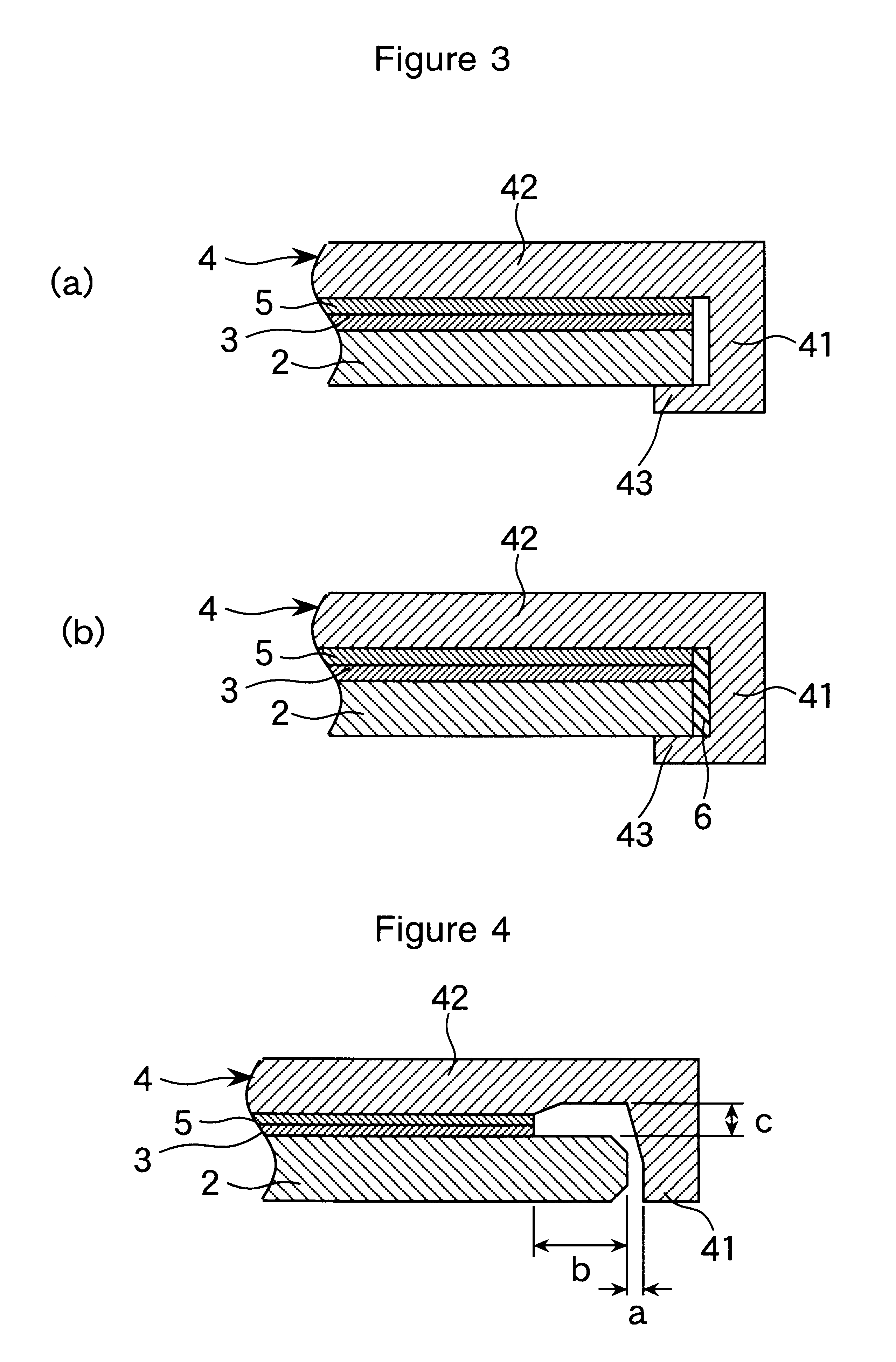
A magneto-optical disc sample No. 2 of the structure shown in FIG. 4 was fabricated. A radial distance a of 0.4 mm was defined between the rim 41 and the glass substrate 2. The space between the protective member rim 41 and the outer side of the glass substrate 2 was not sealed with a resin sealant 6. An additional space was defined between the covering portion 42 and the glass substrate 2 over a radial width b of 2.8 mm from the periphery of the glass substrate 2 and at a spacing c of 0.25 mm between the covering portion 42 and the glass substrate 2. The remaining components are the same as in sample No. 1.

A comparative sample No. 102 was fabricated by the same procedure as sample No. 2 except that the glass substrate 2 was in close fit with both the rim 41 and the covering portion 42.

Similarly these samples, Nos. 2 and 102, were allowed to fall under gravity on the plastic tile floor from a height of 1.5 m. In inventive sample No. 2, none of ten specimens on test failed. In compar...


PUM

PropertyMeasurementUnit
distanceaaaaaaaaaa
distanceaaaaaaaaaa
diameteraaaaaaaaaa

Abstract

The invention provides an optical disc comprising a circular glass substrate (2) having information-carrying means (3) on one major surface. A protective member (4) of a resin includes a circular flat portion (42) and an annular rim (41) extending perpendicular from the periphery of the flat portion (42). The glass substrate (2) is integrally joined to the protective member (4) such that the information-carrying means (3) of the glass substrate (2) may face the covering portion (42) of the protective member (4). The outer side of the glass substrate (2) is surrounded by the protective member rim (41) to leave a shock absorbing space therebetween. The invention prevents the glass substrate from failure at its corner when impact is applied to the disc.

Description

1. Technical FieldThis invention relates to an optical disc. The optical disc includes optical recording discs such as, for example, magneto-optical discs, phase change type optical recording discs, and write-once optical recording discs as well as read-only optical discs.2. Background ArtIn general, optical discs have information-carrying means in the form of a recording layer or a row of pits on one surface of a substrate. For writing and reading purposes, a light beam, typically a laser beam is directed to the information-carrying means from the rear surface of the substrate. The substrate is generally made of a transparent material for this reason. In the prior art, resin substrates are generally used in order to reduce the disc weight and facilitate formation of grooves and pits for tracking and other purposes.Over the recent past, active research has been made on optical discs that carry moving picture digital information. To this end, it is essential to increase the capacity ...

Claims


Application Information

Patent Timeline
Patent Type & Authority Patents(United States)
IPC IPC(8): G11B7/24G11B7/2403G11B7/24053G11B7/24097
CPCG11B7/2403G11B7/24053G11B7/24097
Inventor HIRATA, HIDEKIUTSUNOMIYA, HAJIMEKURIBAYASHI, ISAMUTANABE, HIROSHI
Owner TDK CORPARATION
Learn More