Duckbill with cutting teeth

Inactive Publication Date: 2001-06-19
VERMEER MFG CO
View PDF18 Cites 10 Cited by
  • Summary
  • Abstract
  • Description
  • Claims
  • Application Information

AI Technical Summary

Benefits of technology

According to a preferred embodiment of the present invention, a directing blade for a directional boring machine is disclosed. The directing blade includes a blade body which extends along the longitudinal axis from an attachment end to a free end. The attachm

Problems solved by technology

However, such drill heads may not be satisfactory for rock or other hard soil conditions.

Method used


Image

  • Duckbill with cutting teeth
  • Duckbill with cutting teeth

Examples


Embodiment Construction

Referring now to the drawing figures in which identical elements are numbered identically throughout, a description of the preferred embodiment will now be provided.

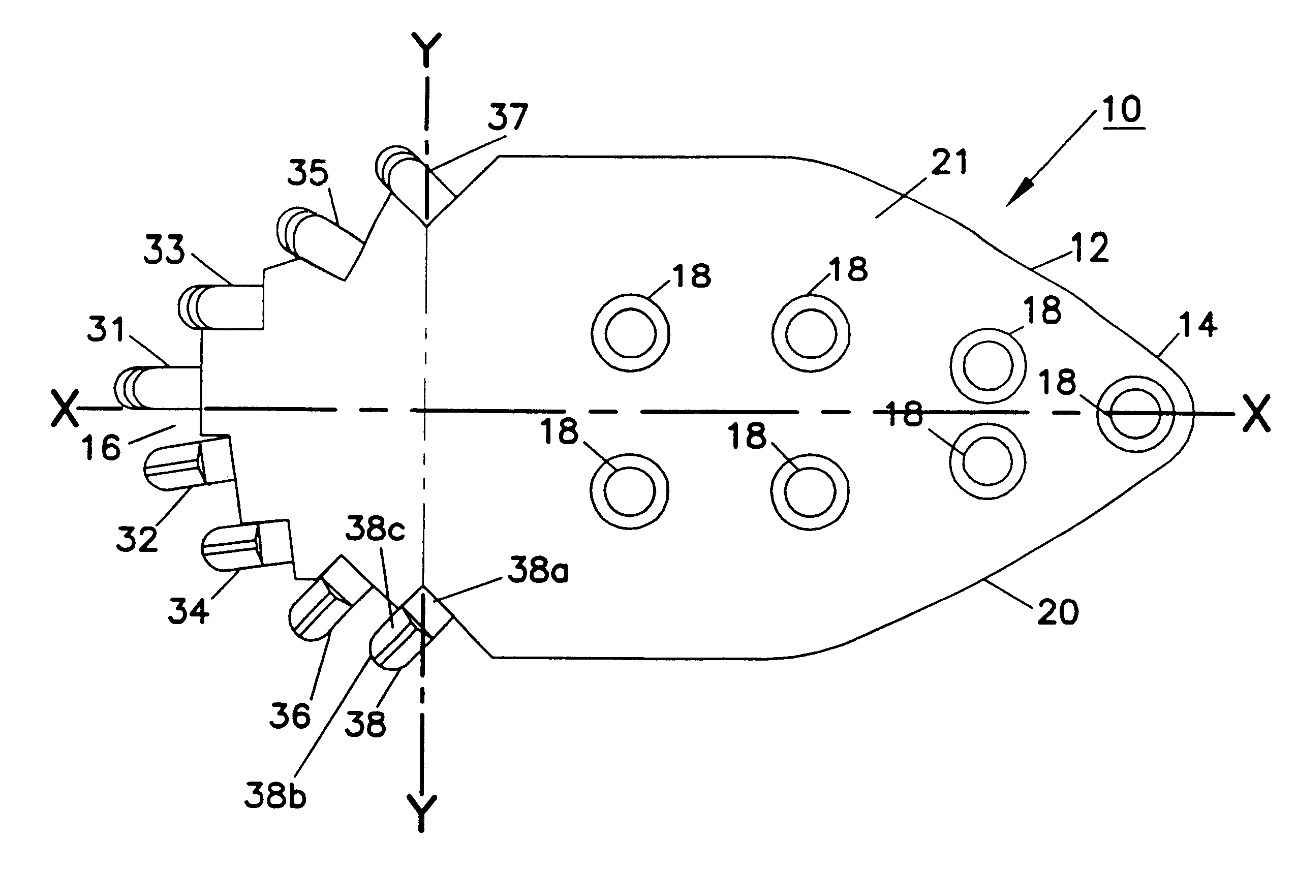
The present invention pertains to a duckbill for attachment to a drill head of a directional boring machine. Such drill heads are provided at the terminal end of a rotary drill string. The drill head has a terminal end and a blade attachment surface for attachment of a duckbill. Such directional boring machines and drill heads having attached duckbills are well known in the art. Examples of such are shown in U.S. Pat. Nos. 4,953,638 and 5,148,880 (incorporated herein by reference).

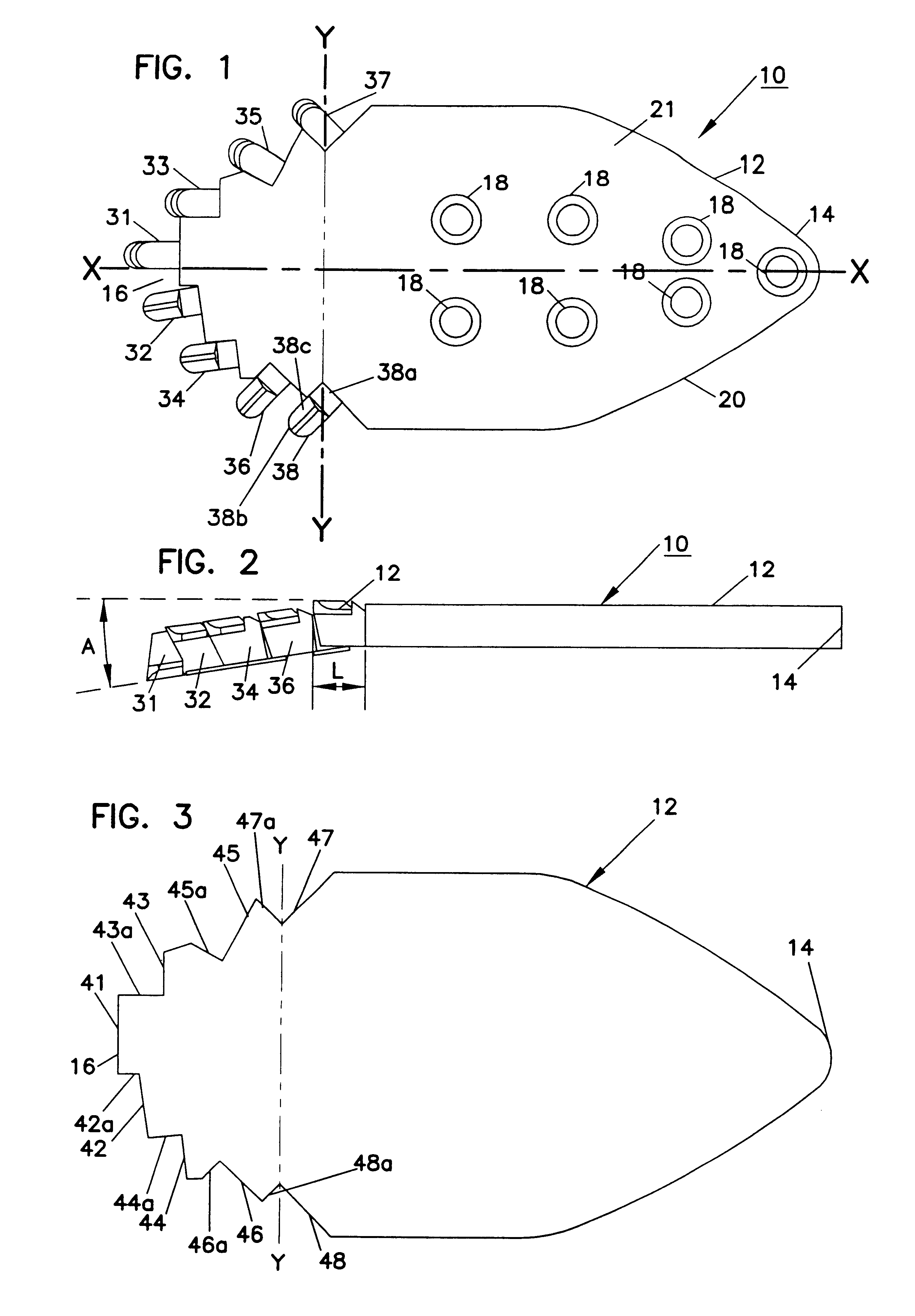
In FIGS. 1 and 2, a novel duckbill (which can also be referred to as a directing blade) is shown. The duckbill 10 is formed of steel and includes a duckbill or blade body 12 extending from an attachment end 14 to a free end 16.

The attachment end 14 includes a plurality of bolt holes 18 placed to match a bolt pattern for attachment to an attachm...


PUM


Abstract

A directing blade for a directional boring machine includes a blade body which extends along a longitudinal axis from an attachment end to a free end. The free end has a plurality of cutting teeth disposed in a non-symmetrical pattern relative to the longitudinal axis. The teeth are progressively spaced from a center portion of the leading end alternating from a first side to a second side of the body of the duckbill blade.

Description

I. BACKGROUND OF THE INVENTION1. Field of the InventionThis invention pertains to directional boring machines. More particularly, this invention pertains to a directional boring machine with a novel duckbill for facilitating penetration of the earth.2. Description of the Prior ArtDirectional boring machines are well known. An example of such a machine is shown in U.S. Pat. No. 4,953,638.In directional boring machines, a plurality of pipe segments are threadedly interconnected to form a drill string. A terminal end of the drill string is provided with a drill head. An above-ground end of the drill string is rotated and longitudinally advanced by a boring machine. Through manipulation of the boring machine, the drill head can be forced through the earth to form a bore. Drill heads come in a variety of shapes and configurations.The '638 patent shows a particular design of a drill head which includes a metal plate (item 72 in FIG. 6) attached to a drill head where the metal plate extend...

Claims


Application Information

Patent Timeline
IPC IPC(8): E21B7/04E21B7/06E21B10/00E21B10/42E21B10/43
CPCE21B7/064E21B10/43E21B10/62
Inventor BEEBE, RANDAL M.
Owner VERMEER MFG CO
Why Eureka
Try Eureka