
Method and apparatus for moving an article relative to and between a pair of thickness measuring probes to develop a thickness map for the article

a technology of thickness measurement and thickness map, which is applied in the direction of resistance/reactance/impedence, measurement devices, instruments, etc., can solve problems such as thickness errors

Inactive Publication Date: 2001-06-05
ADE CORPORATION
View PDF9 Cites 10 Cited by
  • Summary
  • Abstract
  • Description
  • Claims
  • Application Information

AI Technical Summary

Benefits of technology

It is another object of the present invention to provide a method and apparatus to move an article relative to and between a pair of distance measuring probes so as to reduce non-linearity related errors without the use of extensive calibrations.

Problems solved by technology

All dual probe measurement gauges experience distance dynamic range non-linearities that cause thickness errors as either or all wafer warp, wafer tilt in mount and mount distortions move the wafer nearer or farther from the probes during the scanning of the wafer between the probes.

Method used


Image

  • Method and apparatus for moving an article relative to and between a pair of thickness measuring probes to develop a thickness map for the article
  • Method and apparatus for moving an article relative to and between a pair of thickness measuring probes to develop a thickness map for the article
  • Method and apparatus for moving an article relative to and between a pair of thickness measuring probes to develop a thickness map for the article

Examples


Embodiment Construction

The Apparatus

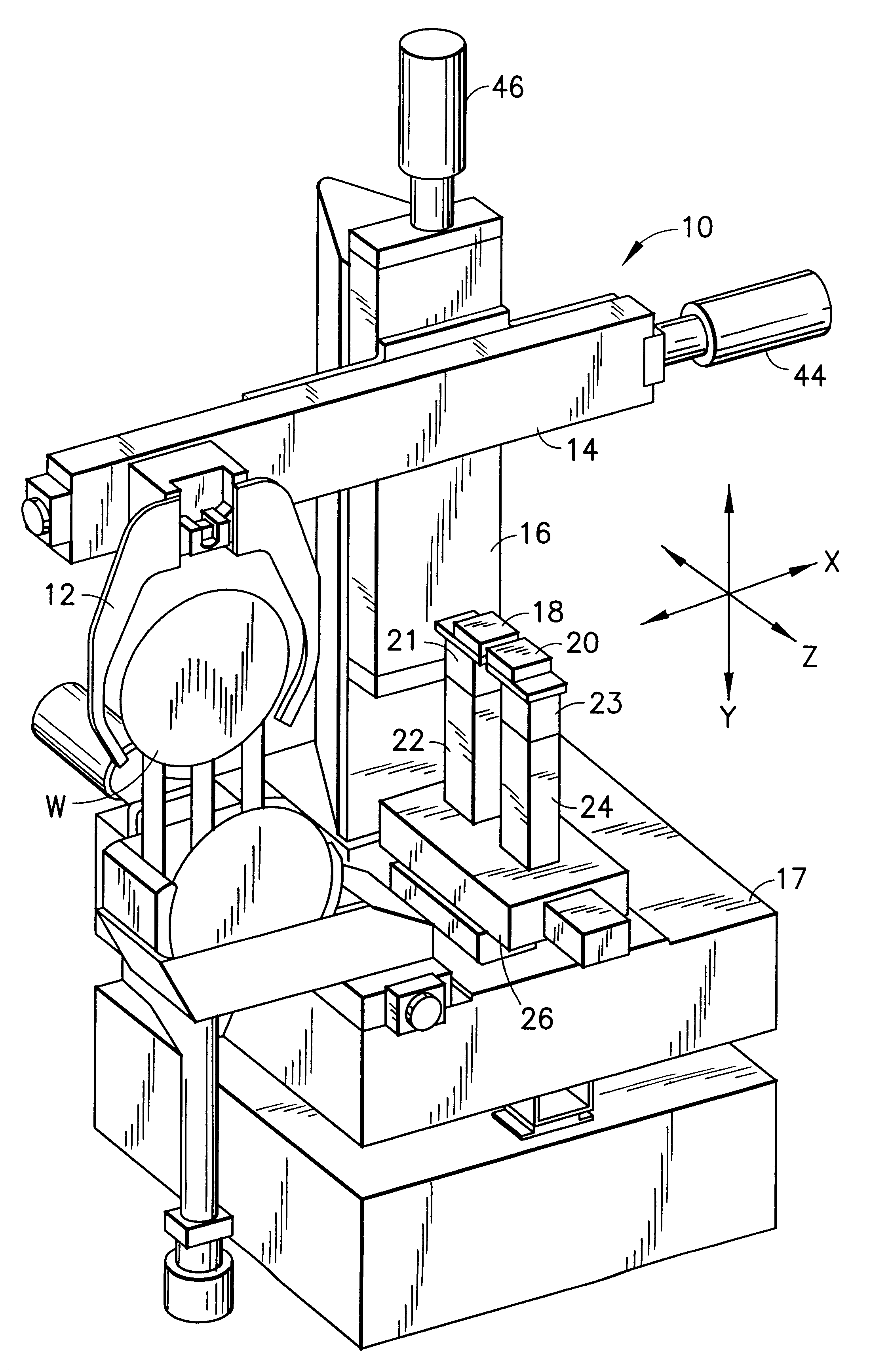
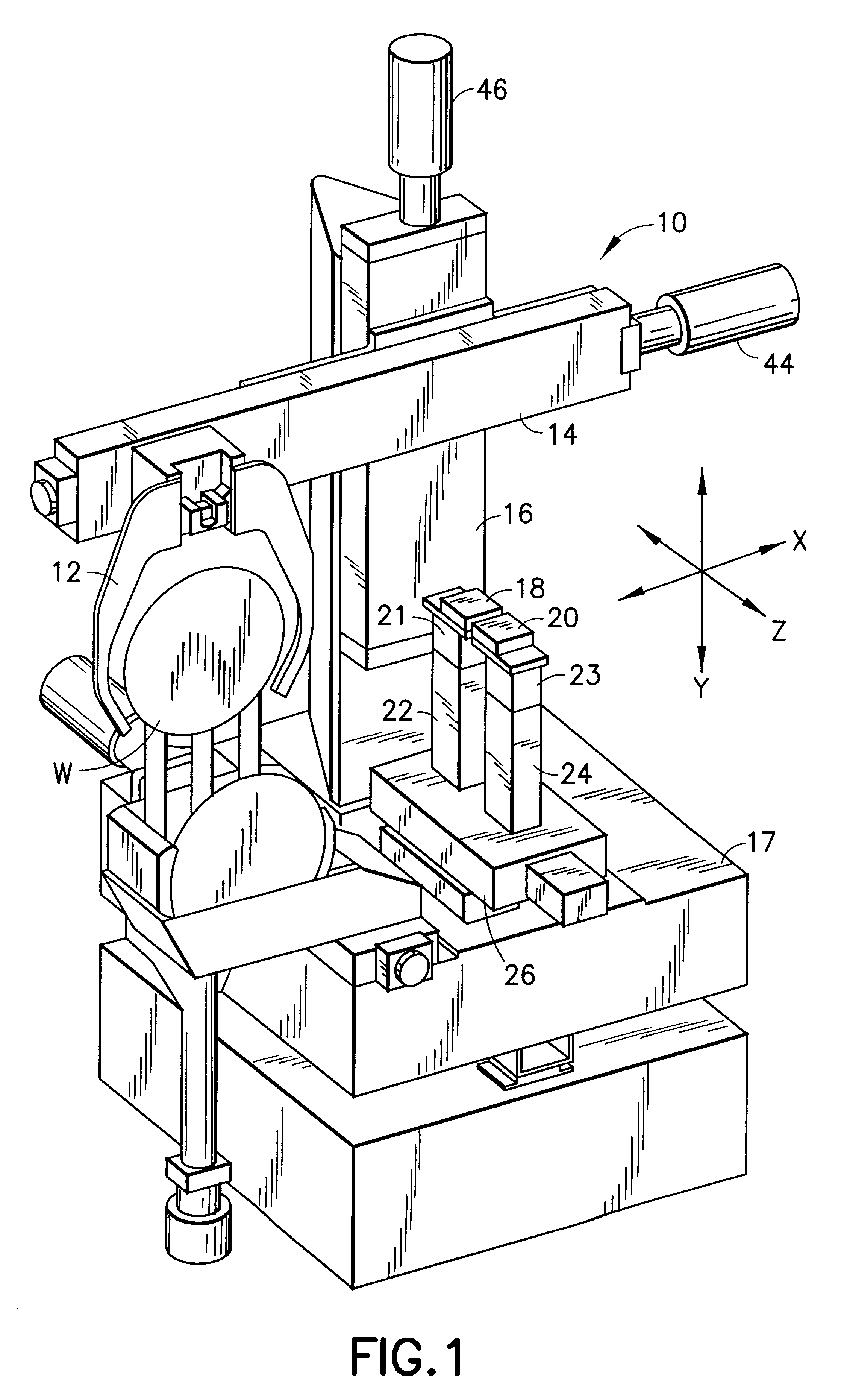
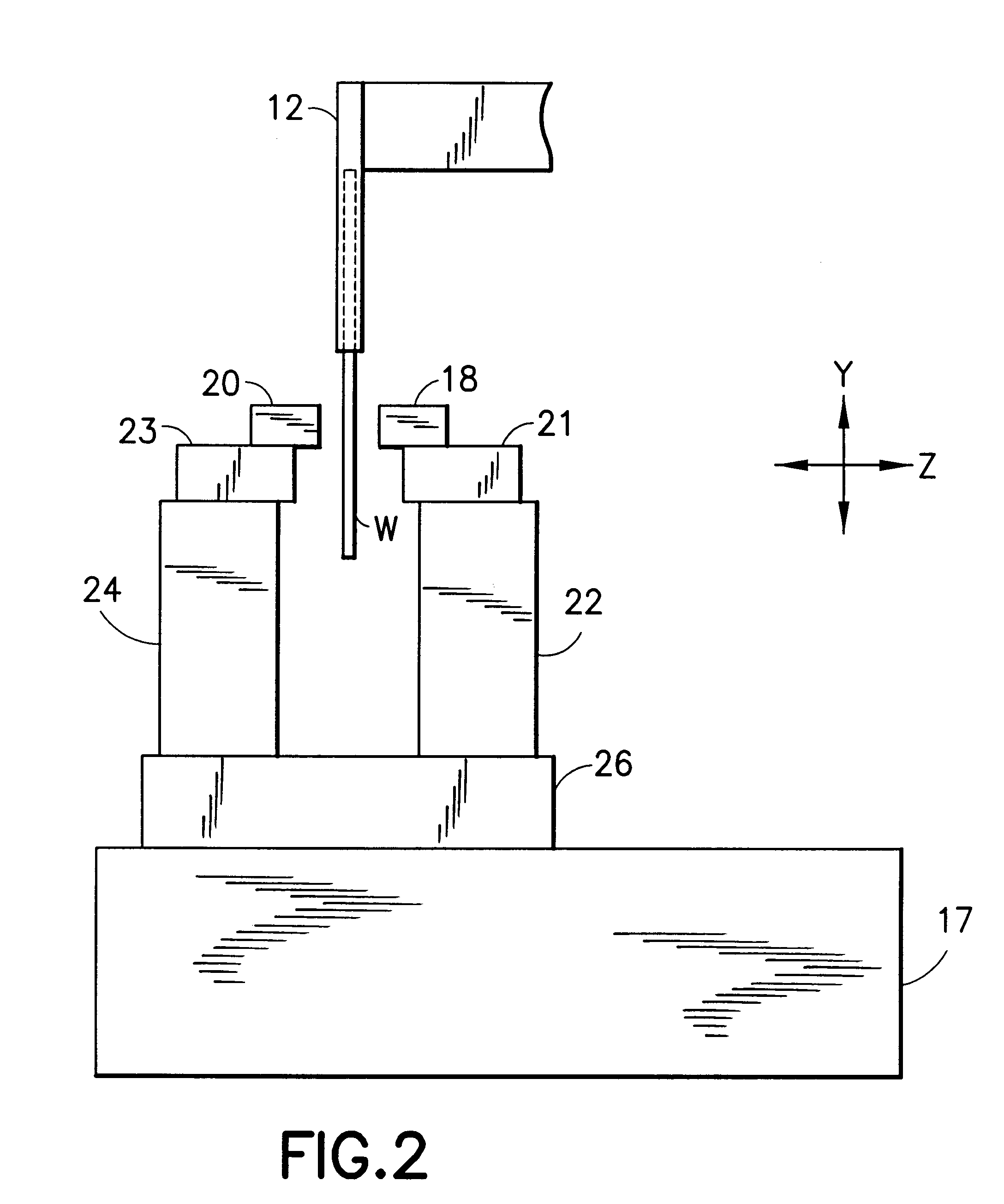
Referring to FIGS. 1 through 3, an apparatus which may be used for determining the thickness, bow and warp of an article, such as a wafer, according to the method of the present invention is generally depicted. The apparatus will be described in the context of measuring the thickness, bow and warp of a wafer. Of course those skilled in the art will appreciate that articles other than wafers can be measured according to the method and apparatus of the present invention.

The apparatus 10 includes an article holder 12 that preferably holds an article, such as wafer W, by its edges. However, the holder 12 may be of a vacuum chuck type which holds the article by applying vacuum to a surface of the article. The holder 12 is mounted on a motorized X-axis translation stage 14. The X-axis translation stage 141 is mounted on a motorized Y-axis translation stage 16 which is attached to base 17. Together, the X-axis and Y-axis translation stages enable the article W to be moved in a...


PUM


Abstract

A method and apparatus for moving an article relative to and between a pair of distance sensing probes of a thickness measuring apparatus which are spaced apart a known distance D is described. In the method, the article is moved relative to and between the pair of probes in at least one direction in a plane normal to a common measurement axis Ac between the probes. A distance a along the common measurement axis Ac between the first probe and a point on the surface of the article nearest to the first probe of the pair that intersects the common measurement axis Ac is measured. A similar distance b between the second probe and the article is measured. From the measured distance a, the article is moved relative to the probes along the common measurement axis Ac so as to minimize any difference between the measured distance a and a desired distance ad along the common measurement axis Ac between the first probe and a point on the surface of the article nearest to the first probe that intersects the common measurement axis. The measured distances a and b and the position of the article relative to the probes in at least one direction are recorded at predetermined time intervals to develop a thickness map of the article. In a thickness computation, all of the measured distances a for each recorded position of the article are substantially the same.

Description

1. Field of the InventionThe present invention generally relates to the measuring of various parameters of thin materials. More particularly, the present invention relates to a method and apparatus for moving an article relative to and between a pair of non-contact thickness measuring probes for the purpose of collecting data about the article which is moved in relation to the probes so that the thickness, bow and warp parameters of the article may be determined.2. Description of the Prior ArtASTM F1530 describes a standard test method for measuring flatness, thickness and thickness variations of semiconductor wafers by noncontact scanning. According to the ASTM test standard, the knowledge of flatness, thickness and thickness variations of semiconductor wafers is useful to both producer and consumer of such wafers to determine if the dimensional characteristics of a given wafer satisfy certain specified geometrical requirements.Under the standard's test method, the above characteri...

Claims


Application Information

Patent Timeline
IPC IPC(8): G01B11/06G01B21/08
CPCG01B11/06G01B21/08G01B2210/44G01B2210/48
Inventor GARDOPEE, GEORGE J.LEDGER, ANTHONY M.GOMEZ, ALEXANDER A.
Owner ADE CORPORATION
Learn More