
Calender for a web, in particular a paper web, process for forming the calender, and process for treating the web with the calender

a technology of calender and web, which is applied in the field of calender for web, can solve the problems of extreme difficulties in fulfilling, nip load generated by the masses of the middle roll and the associated auxiliary devices is essentially completely cancelled out, and the edge or the middle of the roll is affected by the pressure load

Inactive Publication Date: 2001-05-08
VOITH PATENT GMBH
View PDF11 Cites 0 Cited by
  • Summary
  • Abstract
  • Description
  • Claims
  • Application Information

AI Technical Summary

Benefits of technology

With the arrangement of the calender in accordance with the features of the present invention, the desired line load may be adjustable in each nip by levers that are loaded by the devices for exerting force. In the present invention, the levers and devices for exerting force are utilized even though they are not necessary for their conventionally known purpose of weight relief. The deflection adjustment rolls on the ends of the roll stack may support the adjustment of the line load and, in particular, permit an evening out of the line load in the direction of the web width.
It may also be advantageous to provide separate drives for the rolls, which substantially prevents lateral deflections of the rolls. Lateral deflections may occur when a single driven roll causes the other rolls to move via friction.
In accordance with still another feature of the present invention, separate drives associated with each of the rolls may be provided. In this manner, lateral deflections of the rolls are substantially prevented.

Problems solved by technology

Further, the nip load generated by the masses of the middle rolls and the associated auxiliary devices is essentially completely canceled out by the devices for exerting force.
Theoretically, the entire influence of gravity can be eliminated in this manner, however, in practical terms, extreme difficulties are caused in fulfilling the above-mentioned conditions.
In particular, if not all rolls have a same deflection due to their weight, then during operation, higher pressure loads occur on either the edges or in the middle of the roll.

Method used


Image

  • Calender for a web, in particular a paper web, process for forming the calender, and process for treating the web with the calender
  • Calender for a web, in particular a paper web, process for forming the calender, and process for treating the web with the calender
  • Calender for a web, in particular a paper web, process for forming the calender, and process for treating the web with the calender

Examples


Embodiment Construction

The particulars shown herein are by way of example and for purposes of illustrative discussion of the embodiments of the present invention only and are presented in the cause of providing what is believed to be the most useful and readily understood description of the principles and conceptual aspects of the present invention. In this regard, no attempt is made to show structural details of the present invention in more detail than is necessary for the fundamental understanding of the present invention, the description taken with the drawings making apparent to those skilled in the art how the several forms of the present invention may be embodied in practice.

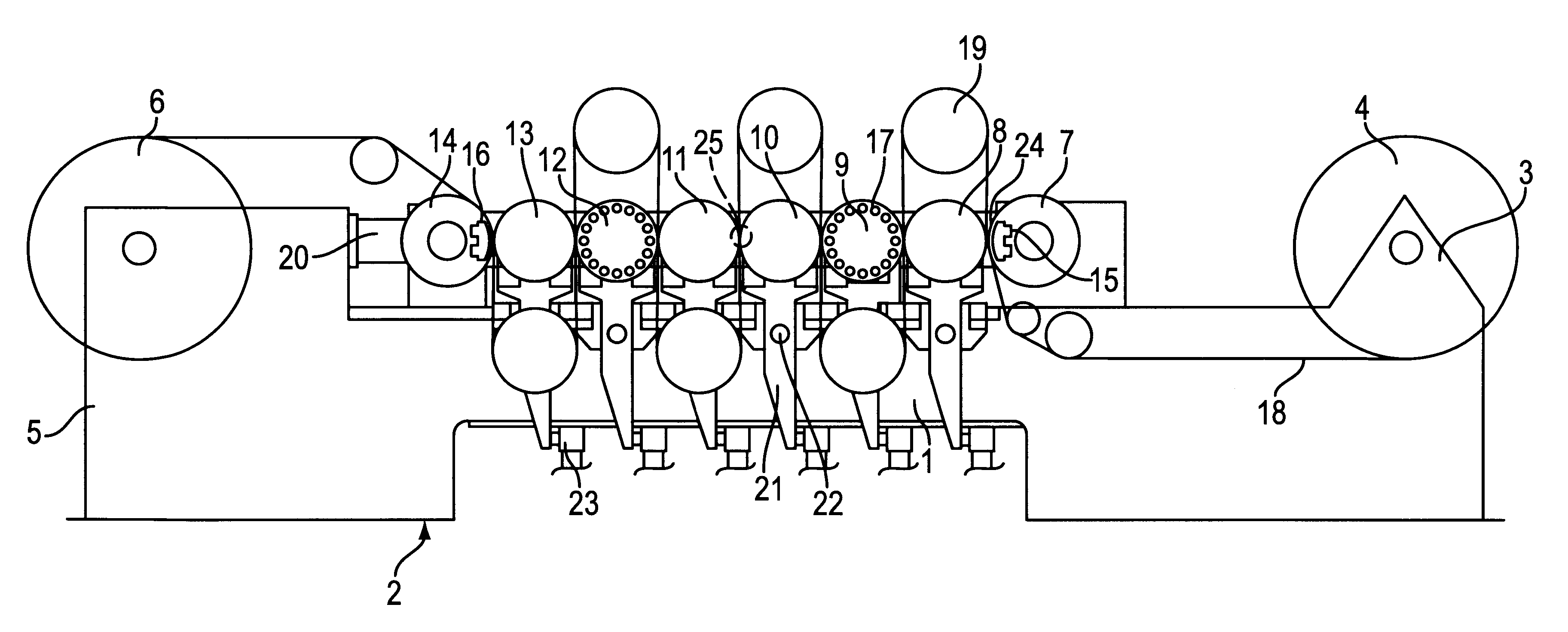
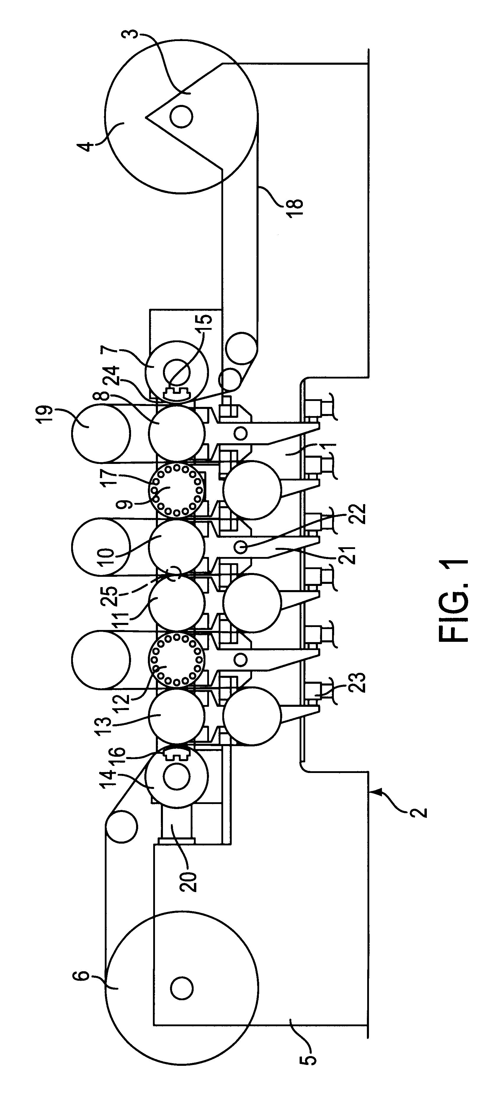
A calender, as schematically illustrated in FIG. 1, includes a frame 1, which is part of a support 2. Frame 1 carries at least one winding station, e.g., an unwinding station 3 for a roll 4 and a winding station 5 for a roll 6. The calender may include a roll stack of, e.g., eight rolls 7, 8, 9, 10, 11, 12, 13, and 14, which ar...


PUM


Abstract

Calender for a web, process of forming the calender, and process of treating a web in the calender. The calender includes rolls having rotational axes and a roll stack composed of the rolls. The rolls of the roll stack are arranged such that the rotational axes are positionable in a horizontal plane. The calender also includes levers. The rolls include end rolls and middle rolls, the middle rolls being coupled to the levers. The calender also includes force devices positioned to exert a force on the levers. The process of forming includes arranging the rotational axes of the rolls in a horizontal plane, coupling levers to the middle rolls arranged between the end rolls of the roll stack, and coupling force devices to the levers. The process of treating the web includes guiding the web through the roll stack, pressing an end roll of the roll stack in a horizontal direction toward the other end roll of the roll stack, and adjusting a line load between adjacent rolls of the roll stack.

Description

1. Field of the InventionThe present invention is related to a calender for a web, e.g., a paper web. The calender includes a stack of rolls having axes that are located in a horizontal plane.2. Discussion of Background InformationConventional type calenders, which include a stack of rolls having horizontal axes that are located one above the other in a vertical plane, are used for treating paper, paperboard, plastic foils, and similar material. The nips are either formed by adjacent hard rolls or, particularly in paper refining, are formed by an adjacent hard roll and soft roll. The line load in the nips is provided by hydraulic force transmitters that engage an end roll of the roll stack and by the weight of the rolls. Thus, the line load, and, therefore, the compressive strain, increases from the top to the bottom of the roll stack. In this regard, the variation range of the forces that can be exerted by the force transmitters is relatively small. Further, a limitation of force t...

Claims


Application Information

Patent Timeline
IPC IPC(8): D21G1/00
CPCD21G1/00
Inventor KAYSER, FRANZ
Owner VOITH PATENT GMBH
Learn More