Computer having a drive unit unifying an FDD and a CD-Rom drive

a drive unit and computer technology, applied in the field of tower-shaped computers, can solve problems such as affecting the work of users, and achieve the effect of improving stability and improving space utilization

Inactive Publication Date: 2001-04-17
HANGER SOLUTIONS LLC
View PDF3 Cites 12 Cited by
  • Summary
  • Abstract
  • Description
  • Claims
  • Application Information

AI Technical Summary

Benefits of technology

The technical effect of this patent is that it describes two new types of computers: one is designed for better use of space, while another improves stability. These improvements make them more efficient and stable than traditional desktop computers, making them easier to work with and handle.

Problems solved by technology

The technical problem addressed in this patent text is that traditional personal computers (both desktop and tower) take up too much room at the expense of the user's workspace. Users often opt for smaller, more efficient tower-shaped computers, especially those designed specifically for use with limited resources. Additionally, there is a preference for uniquely designed computers over ones with a common appearance.

Method used


Image

  • Computer having a drive unit unifying an FDD and a CD-Rom drive
  • Computer having a drive unit unifying an FDD and a CD-Rom drive
  • Computer having a drive unit unifying an FDD and a CD-Rom drive

Examples


Embodiment Construction

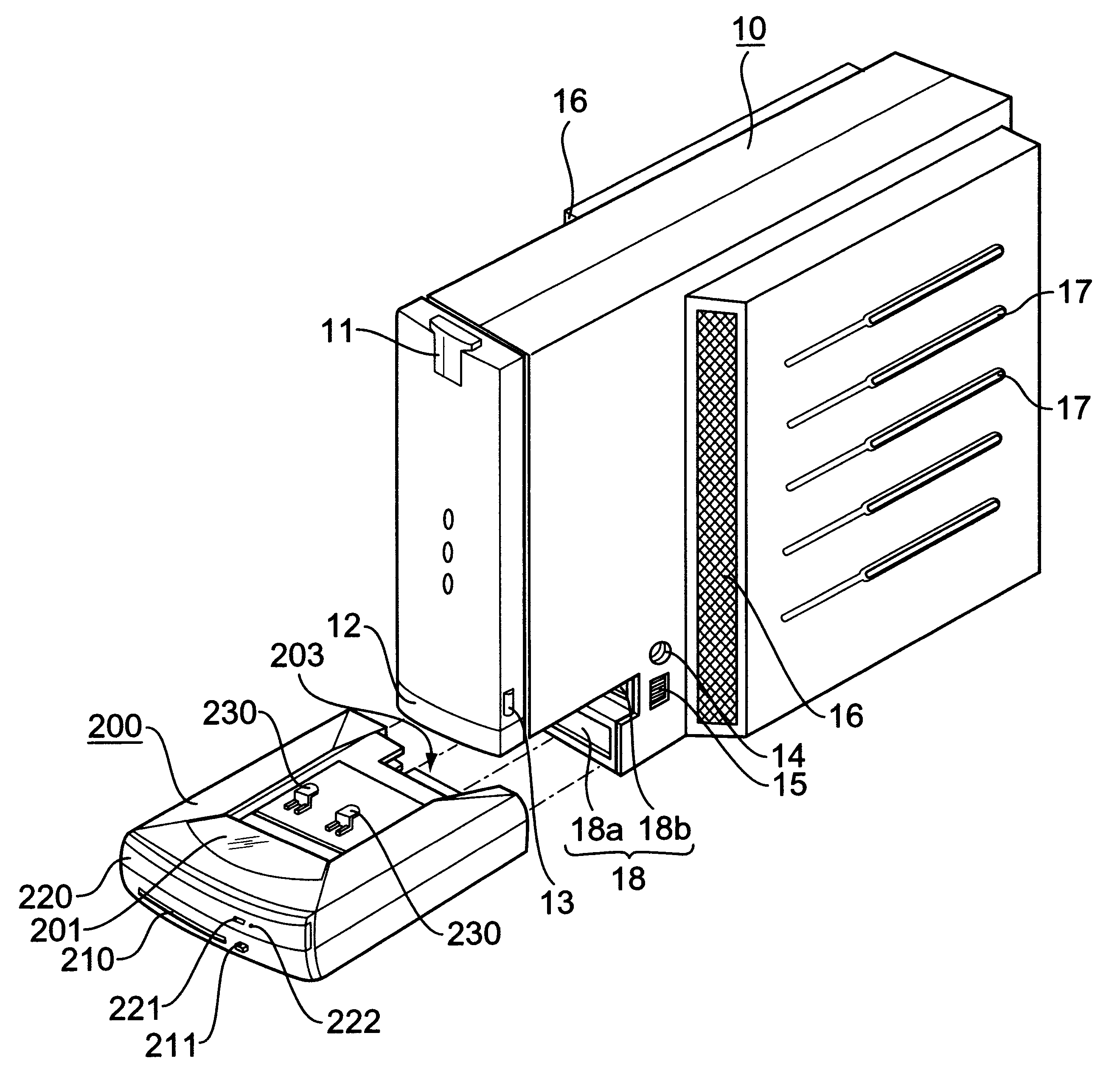
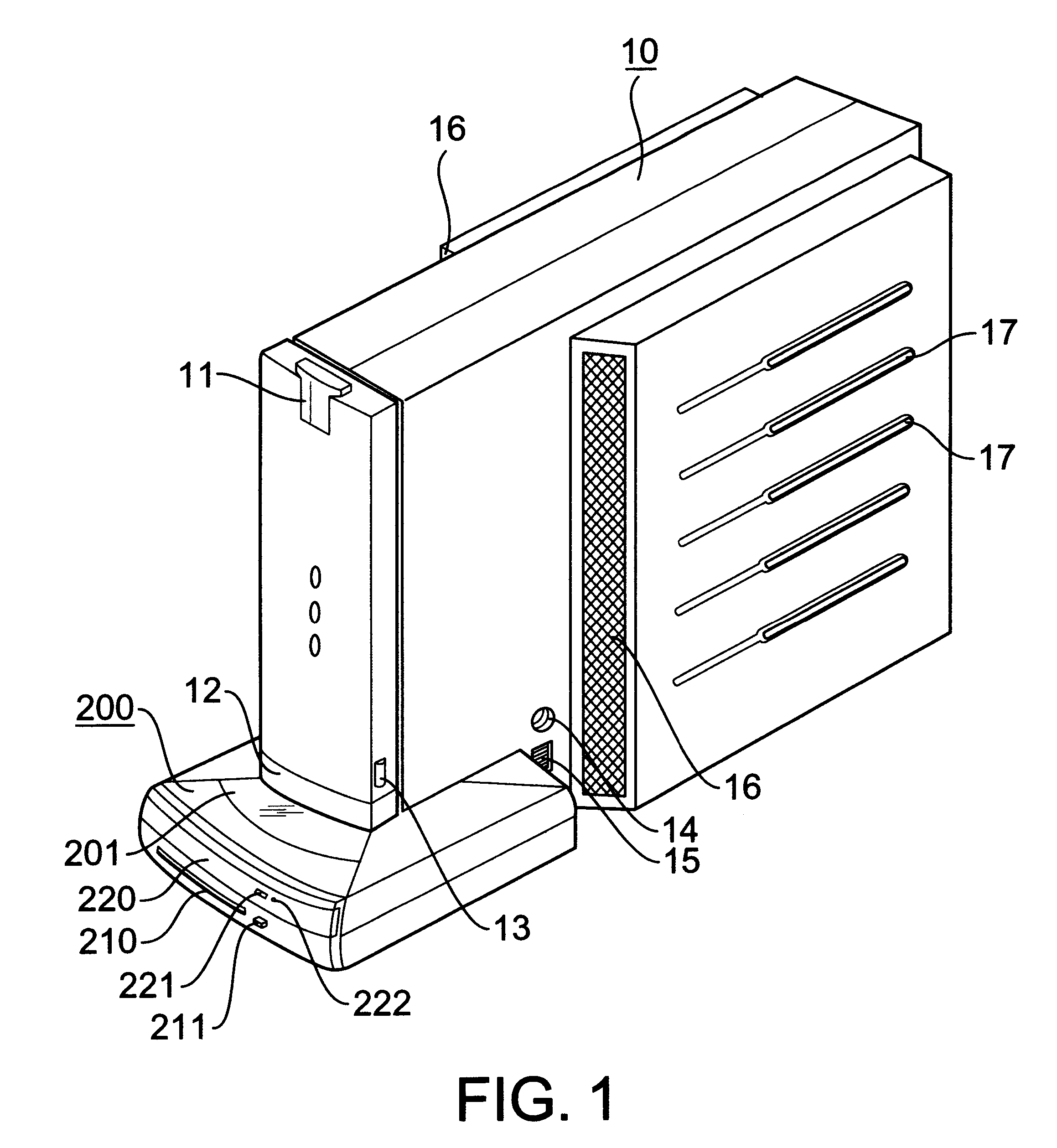
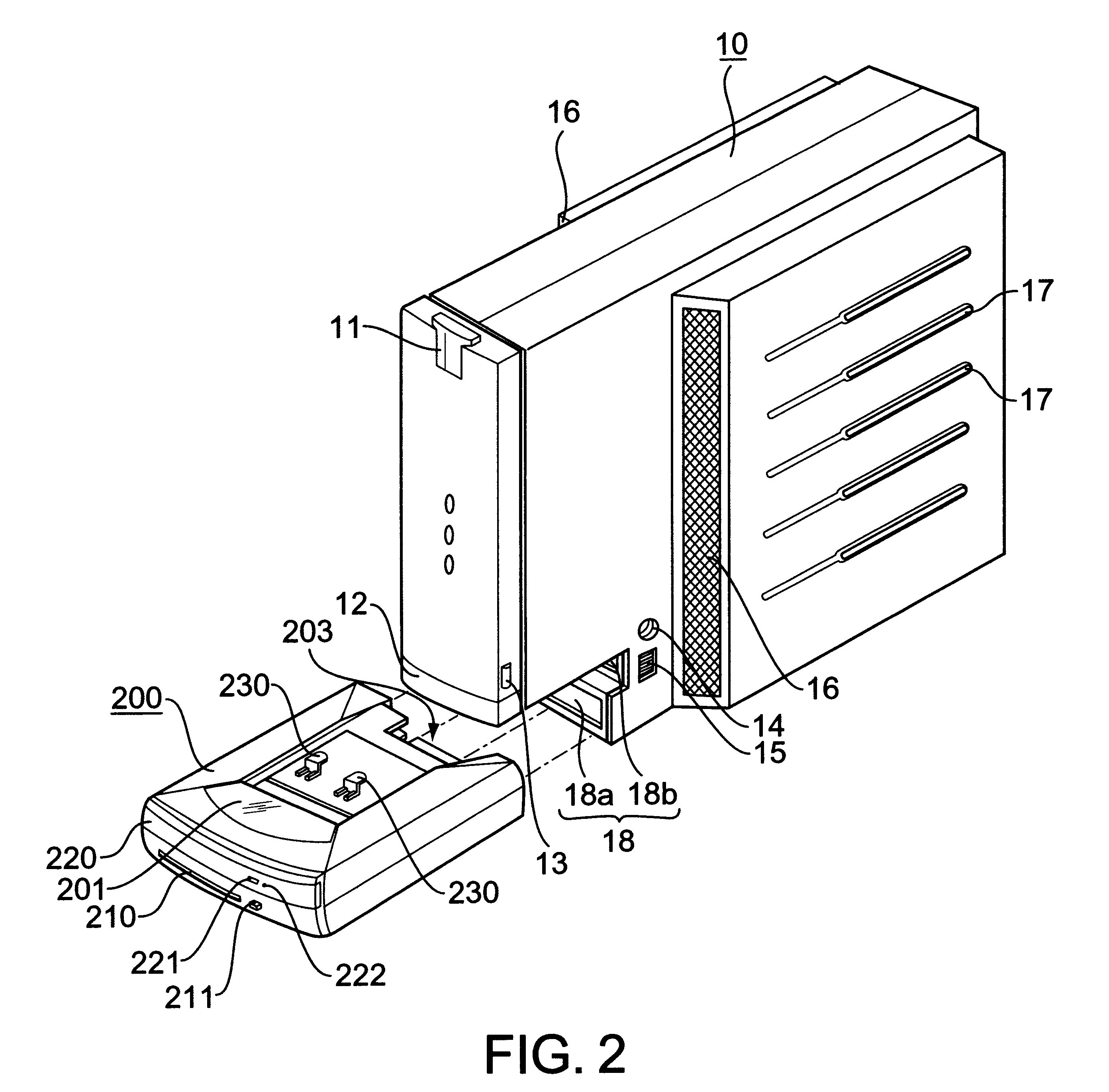
The present invention will be apparent from the following description in detail in conjunction with the accompanying drawings. FIG. 1 is a perspective view of a tower-shaped computer according to the present invention and FIG. 2 is a perspective view illustrating a separated state of a drive unit from a computer body in the computer illustrated in FIG. 1.

Referring to FIG. 1 and FIG. 2, this invention is a tower-shaped computer having the body 10 in an upright position. There are provided various circuits inside of the body 10 as are well known in the art. There is provided a power switch 11 for supplying and cutting power to the computer in the upper part of the front face of the body 10. The power switch 11 is a pushbutton switch. In addition, the power switch 11 is made of semi-transparent material so that a light emitting diode provided in the inside can be seen from the outside. The switch is preferably made of colored transparent material, so that the power switch 11 is colored...


PUM


Abstract

A tower-shaped computer having a drive unit unifying an FDD (Floppy Disk Drive) and a CD-ROM drive (Compact Disk-Read Only Memory) horizontally on the lower part to improve the utility of the space effectively. There is provided a computer comprising a body having a receptacle in a lower part of a front face and a plurality of input-ports provided at a rear side of the receptacle; a drive unit being received in the receptacle such that a front portion thereof is protruded from the front face of the body, the drive unit includes a floppy disk drive integrated with a compact disk read-only memory drive and output ports positioned at a rear side thereof and connected to the input ports, respectively.

Description


Claims


Application Information

Patent Timeline
Owner HANGER SOLUTIONS LLC
Why Eureka
Try Eureka