Flotation system and method for off-shore platform and the like
a technology of offshore platforms and plotting systems, which is applied in the direction of special-purpose vessels, vessel construction, transportation and packaging, etc., can solve the problems of high maintenance costs of steel structures, increased life cycle cost, and prone to corrosion of steel structures in the marine environmen
- Summary
- Abstract
- Description
- Claims
- Application Information
AI Technical Summary
Problems solved by technology
Method used
Image
Examples
third embodiment
the present invention is designated generally as 200 and is shown in FIGS. 16 through 19. This flotation assembly 200 is in the form of a SPAR and comprises a hull 202, a SPAR frame 204 and a flotation apparatus 206 which in this embodiment can be considered to be a flotation module. The hull 202 and the SPAR frame 204 are fixedly connected to one another and act as a unit while the flotation module 206 is positioned within the hull 202 and the frame 204, and is able to move vertically independently of the hull 202 the SPAR frame 204.
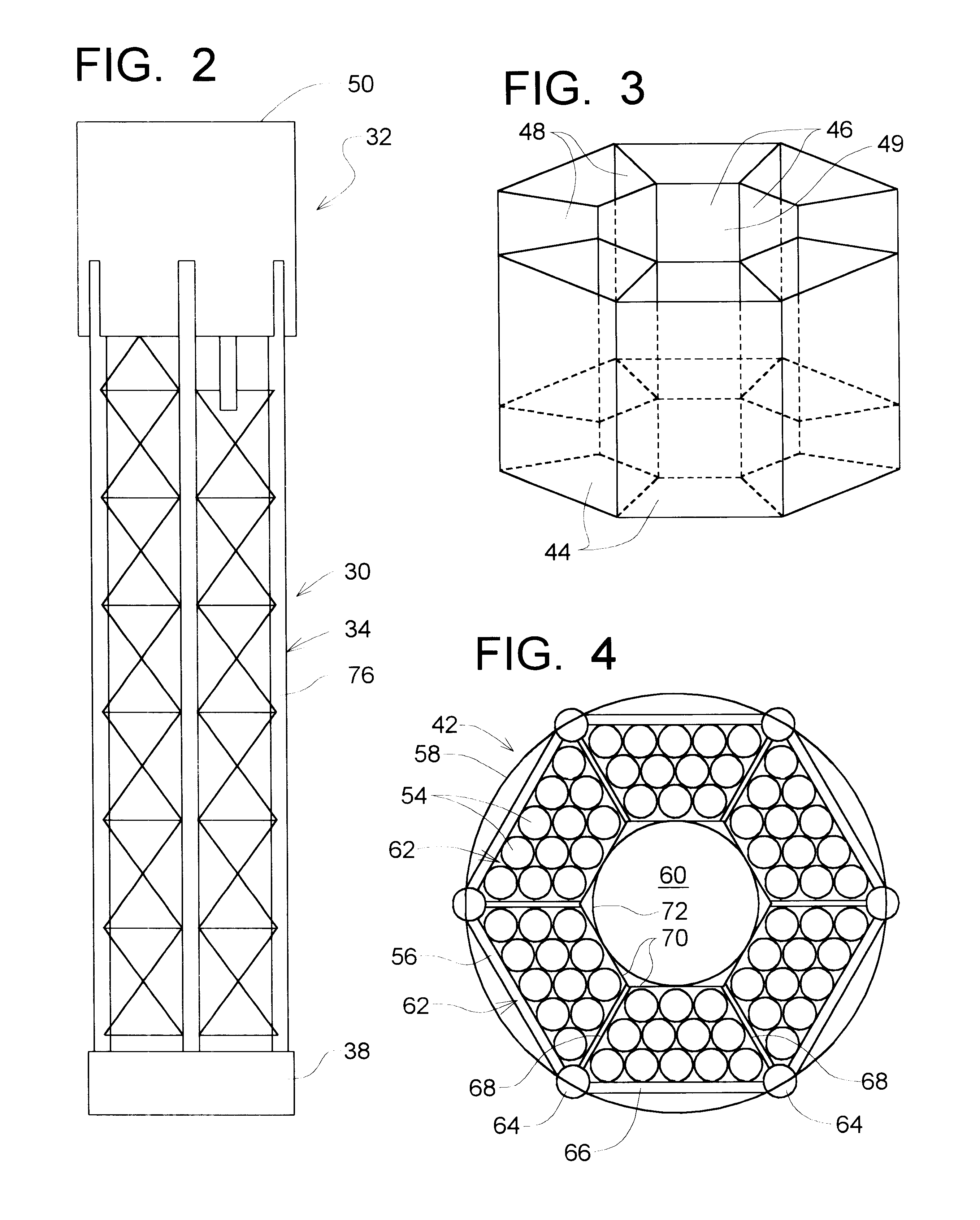
In this particular embodiment, the hull 202 can be a conventional hull (or a nearly conventional hull) where the volume of the hull is sufficiently great so that it is able to float both the hull 202 and the SPAR frame 204. Also, as an alternative, the hull 202 could be replaced with a flotation assembly such as that shown as 32 in FIGS. 2 and 5.
To describe now the flotation apparatus 206, there is first a central section 208 which extends from a lower ...
fourth embodiment
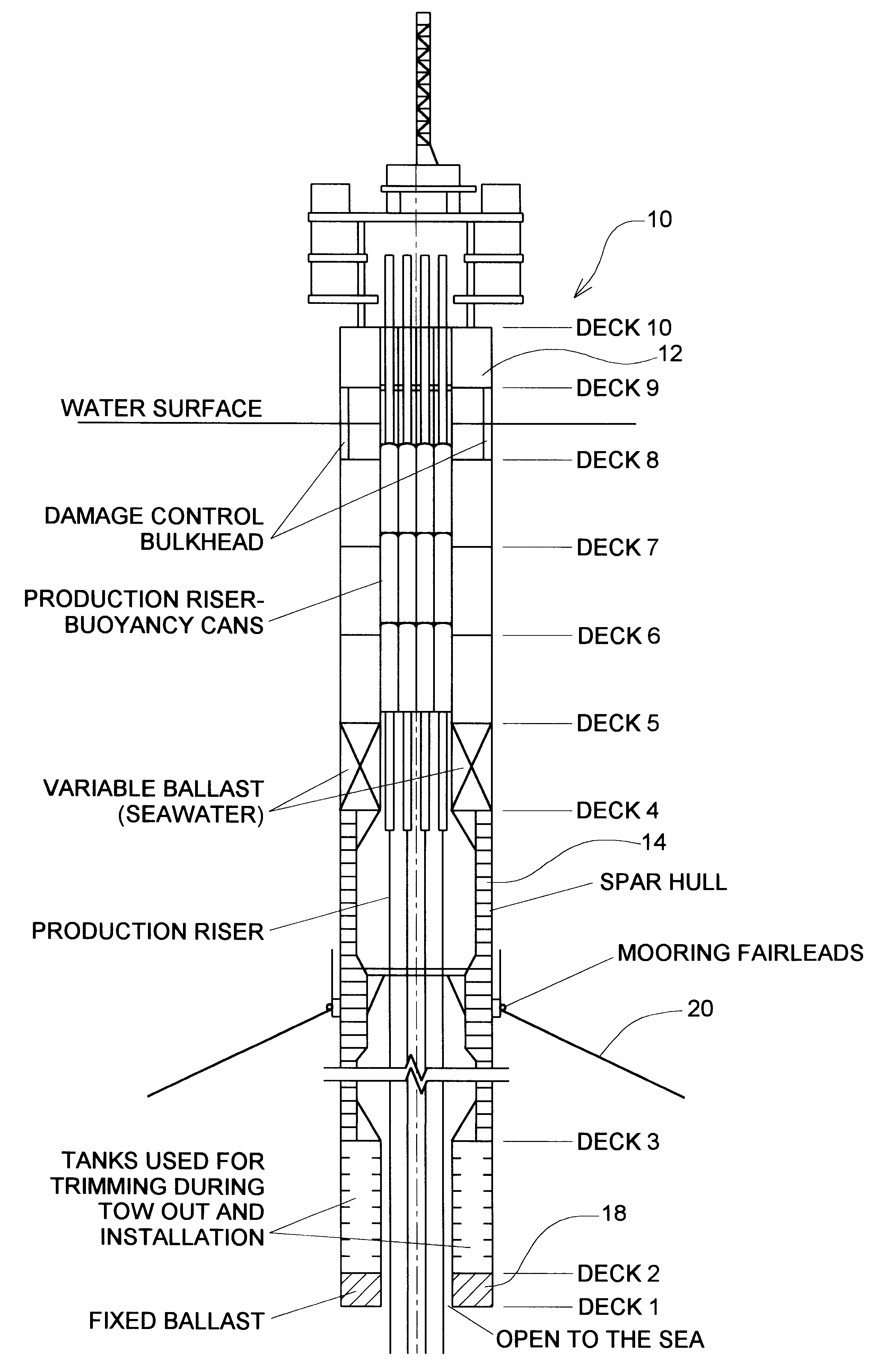
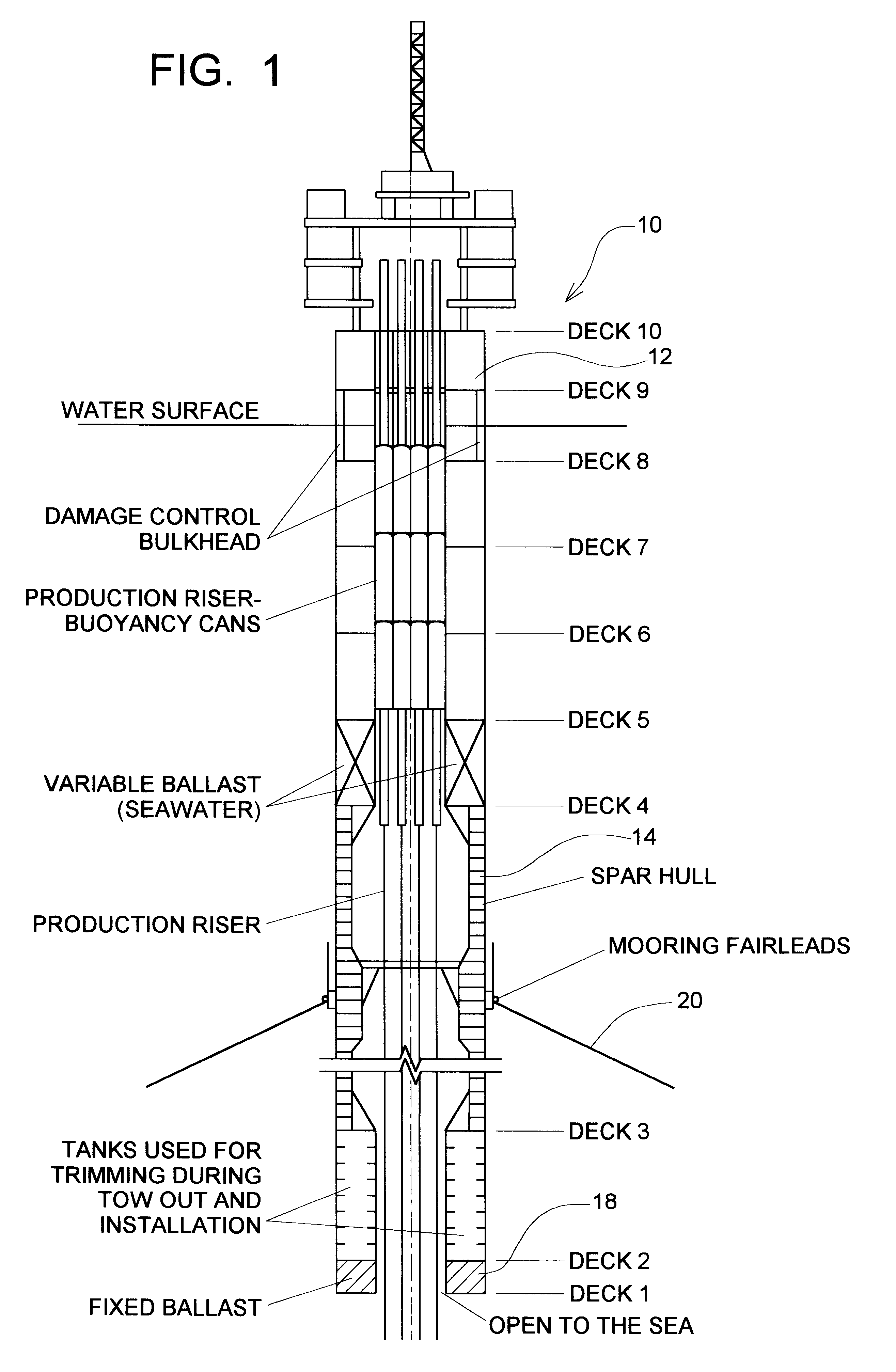
This fourth embodiment will now be described with references to FIGS. 20, 21 and 22. The situation for which this fourth embodiment is particularly adapted is where there is an existing prior art SPAR and the flotation capacity of the existing SPAR is not adequate to meet increased performance demands, in that the additional weight created by equipment, risers, etc. exceed the present flotation capacity of the SPAR.
As shown in FIG. 22, the SPAR 260 comprises the hull 262 and the SPAR truss 264 and the ballast section 266. To provide the additional support, there is added to the hull 262 at an intermediate location a surrounding annular, horizontally aligned flange 267. Attached to the outer edge of the flange 267 and extending downwardly therefrom is a surrounding cylindrical shroud 268 which provides an annular flotation space 269 between the shroud 268 and the radially inward cylindrical outer surface portion 270 of the hull 262.
Positioned in this flotation space 269 is a pluralit...
fifth embodiment
The fifth embodiment is shown in FIGS. 23 through 27. This fifth embodiment is similar to the first embodiment as shown in FIGS. 2 and 5, except that the conventional hull of the first embodiment has been replaced with a support structure which is positioned at or above the water surface.
In this fifth embodiment, there is a SPAR 290 comprising an upper flotation section 292, a SPAR truss 294, and a lower ballast section 296. The flotation assembly 292 comprises an upper annular support structure 298, an upper group 300 of flotation tubes 302, a lower group 304 of flotation tubes 306, and upper and lower shroud sections 308 and 310, respectively. The support structure 298 and the upper and lower flotation tube groups 300 and 304 define a central through opening 305.
As can be seen in FIG. 23, the arrangement of the upper group 300 flotation tubes 302 is substantially in the same arrangement as shown in FIG. 4 of the first embodiment. Thus, there are vertical columns 311 in a hexagonal...
PUM
| Property | Measurement | Unit |
|---|---|---|
| elevation | aaaaa | aaaaa |
| depth | aaaaa | aaaaa |
| depth | aaaaa | aaaaa |
Abstract
Description
Claims
Application Information
 - R&D
- Intellectual Property
- Life Sciences
- Materials
- Tech Scout
- Unparalleled Data Quality
- Higher Quality Content
- 60% Fewer Hallucinations
Browse by: Latest US Patents, China's latest patents, Technical Efficacy Thesaurus, Application Domain, Technology Topic, Popular Technical Reports.
© 2025 PatSnap. All rights reserved.Legal|Privacy policy|Modern Slavery Act Transparency Statement|Sitemap|About US| Contact US: help@patsnap.com


