
Method and system for determining an absolute power loss condition in an internal combustion engine

an absolute power loss and internal combustion engine technology, applied in the field of recreating internal combustion engines, can solve the problems of increased down time and excess exhaust emissions, power loss can be caused, and excessive exhaust emissions are extremely problemati

Inactive Publication Date: 2001-03-06
CATERPILLAR INC
View PDF6 Cites 87 Cited by
  • Summary
  • Abstract
  • Description
  • Claims
  • Application Information

AI Technical Summary

Problems solved by technology

Power loss conditions in internal combustion engines present several problems, including increased down time and excess exhaust emissions.
Excess exhaust emissions are extremely problematic since government regulations are making more stringent demands or limits on the exhaust emissions of internal combustion engines (diesel or spark ignited).
Power loss can be caused by complete and / or partial misfires or clogged fuel injectors.
The presence of these vast training data sets creates an extraordinary burden in determining a multiple-cylinder or all-cylinder power loss condition.

Method used


Image

  • Method and system for determining an absolute power loss condition in an internal combustion engine
  • Method and system for determining an absolute power loss condition in an internal combustion engine
  • Method and system for determining an absolute power loss condition in an internal combustion engine

Examples


Embodiment Construction

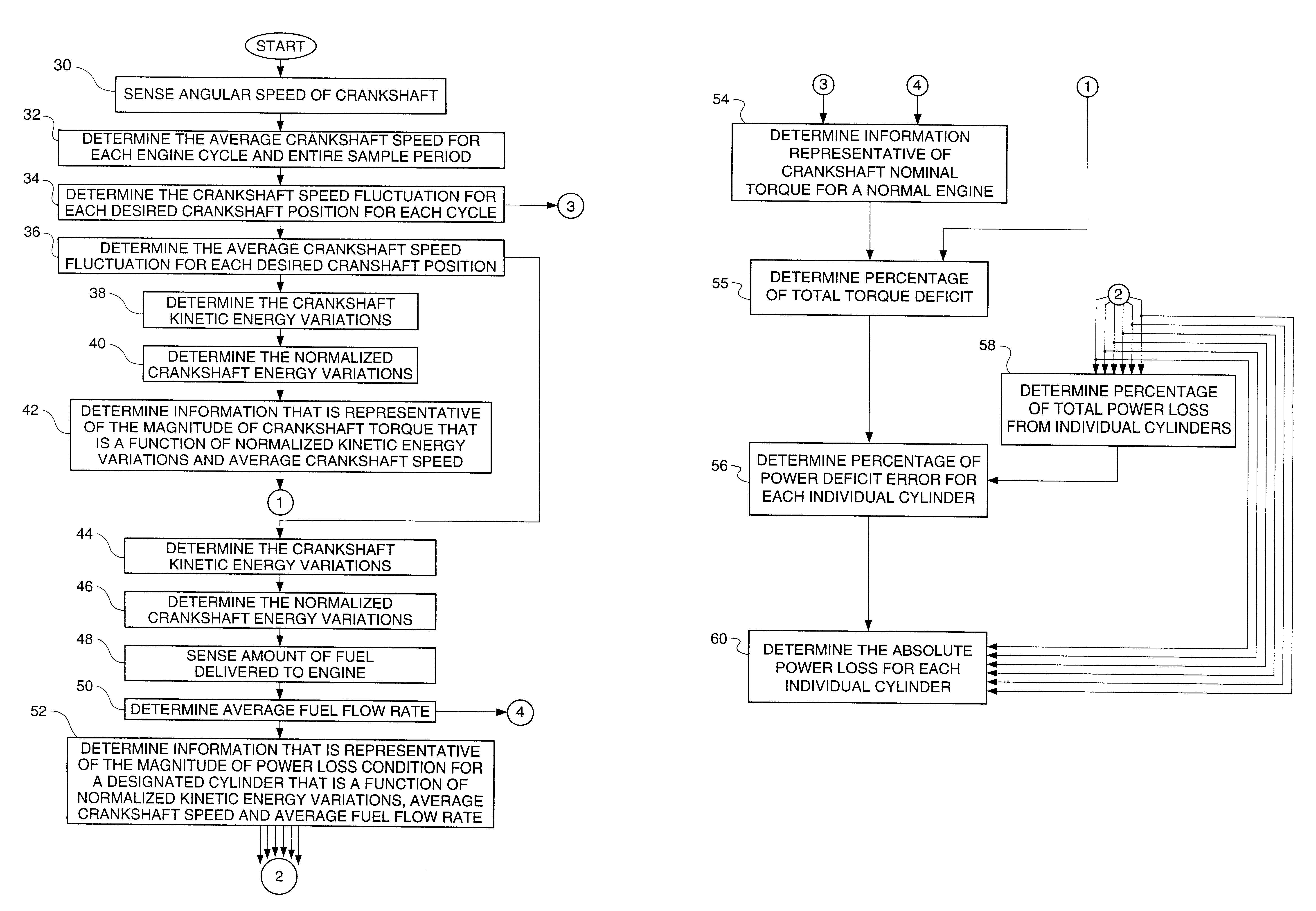
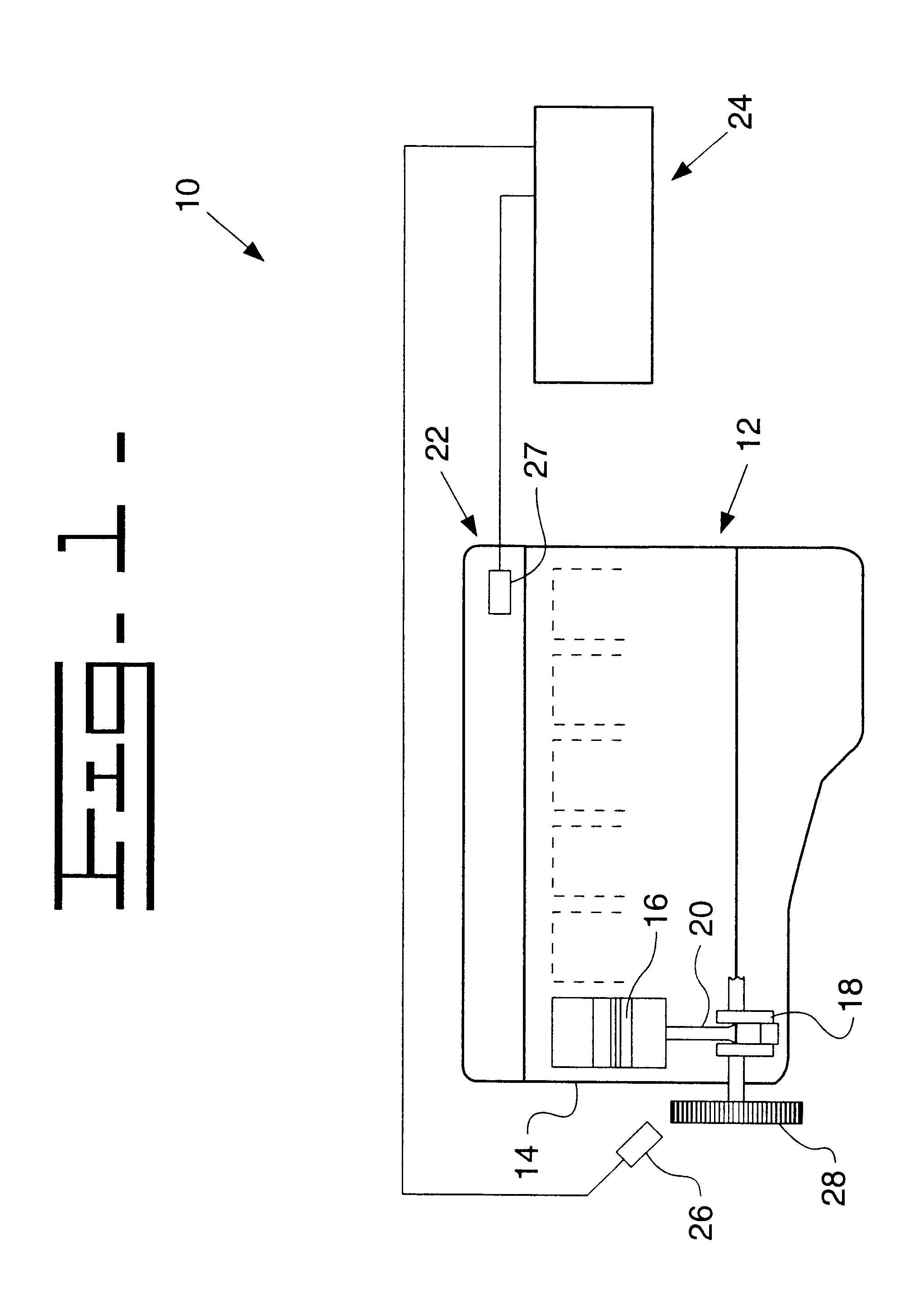
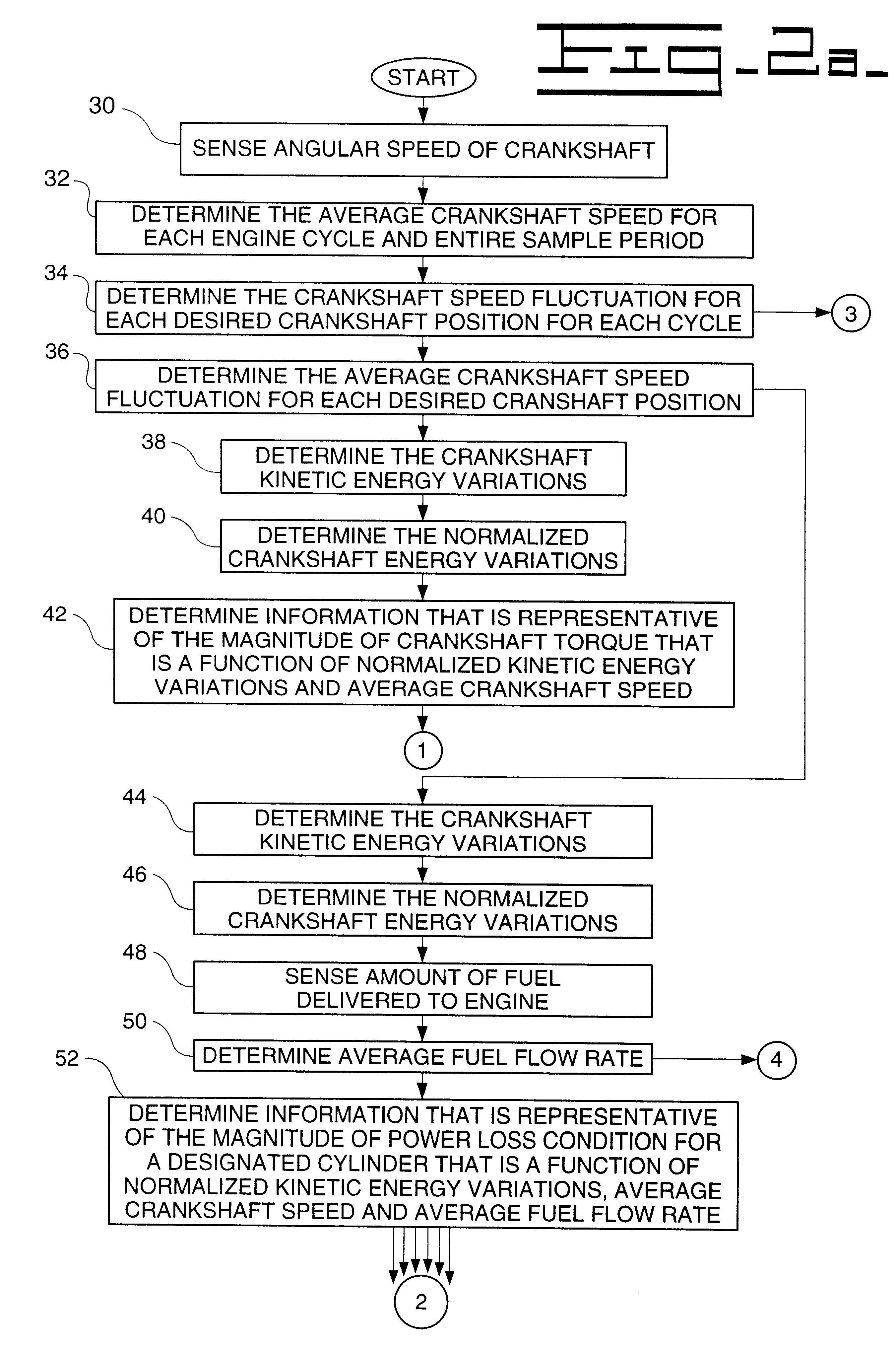
Referring now to the drawings, and initially to FIG. 1, an electronic control system 10 is depicted for determining an absolute power loss for a cylinder 14 of an internal combustion engine 12. The power loss condition typically indicates degradation of an individual cylinder 14. This can be due to a complete or partial misfire, clogged fuel injector, or some other problem. Preferably, the internal combustion engine 12 can be a six cylinder, compression ignited, diesel engine. However, any of a wide variety of both spark ignited and compression-ignited engines, having one or more cylinders, can be utilized with the present invention. Each of the cylinders, as represented by numeral 14, has a piston 16 reciprocally moveable therein. Each piston 16 is connected to a rotatable crankshaft 18 by a connecting rod 20 for rotating the crankshaft 18. Fuel delivery from a fuel source (not shown) to the individual cylinders of the internal combustion engine 12 can be controlled by a governor 2...


PUM


Abstract

A method and system for detecting absolute power loss in a cylinder for a reciprocating internal combustion engine, the internal combustion engine having at least one cylinder and a rotatable crankshaft. This method and system includes sensing rotational crankshaft speed for a number of designated crankshaft rotational positions over a predetermined number of cycles of rotation for each of the crankshaft positions and determining an average crankshaft speed fluctuation for each of the crankshaft positions and determining information representative of crankshaft kinetic energy variations due to each firing event or each firing event and compression event in said cylinder and determining information representative of an average fuel flow rate and determining information representative of power loss for the cylinder as a function of the crankshaft kinetic energy variations due to each firing event, the average crankshaft speed and the average fuel flow rate and responsively producing a representative power loss signal and determining information representative of crankshaft torque as a function of the crankshaft kinetic energy variations due to each firing event and compression event and the average crankshaft speed and responsively producing a representative crankshaft torque signal and determining information representative of absolute power loss for each cylinder.

Description

TECHNICAL FIELDThis invention relates generally to a reciprocating internal combustion engine, and more particularly, to a method and system for determining an absolute power loss condition in an internal combustion engine.BACKGROUND ARTPower loss conditions in internal combustion engines present several problems, including increased down time and excess exhaust emissions. Excess exhaust emissions are extremely problematic since government regulations are making more stringent demands or limits on the exhaust emissions of internal combustion engines (diesel or spark ignited). Power loss can be caused by complete and / or partial misfires or clogged fuel injectors. The detection of an all-cylinder or absolute power loss condition in each cylinder requires numerous data sets being available for training in order to evaluate each and every cylinder. The presence of these vast training data sets creates an extraordinary burden in determining a multiple-cylinder or all-cylinder power loss ...

Claims


Application Information

Patent Timeline
IPC IPC(8): G01M15/00G06F19/00
CPCG01M15/05
Inventor ZAVAREHI, MASOUD K.SCHRICKER, DAVID R.
Owner CATERPILLAR INC
Learn More