Tracking control method for optical storage apparatus using near field optical effect and optical probes

a tracking control and optical storage technology, applied in the field of optical storage, can solve the problems of difficult realization, inability to read the information recorded on the recording medium, and the optical spot being smaller than the wavelength of the incident rays

Inactive Publication Date: 2001-02-06
LG ELECTRONICS INC
View PDF7 Cites 12 Cited by
  • Summary
  • Abstract
  • Description
  • Claims
  • Application Information

AI Technical Summary

Problems solved by technology

It is impossible for the optical spot to be smaller than the wavelength of the incident rays because of optical diffraction effect.
This is difficult to realize actually.
Thus, it cannot read the information recorded on the recording medium because of the track direction and scanning direction out of accordance with each other.
However, this optical storage could not completely correct the error because the track and scanning line for every recording medium are difficult to accord with each other.

Method used


Image

  • Tracking control method for optical storage apparatus using near field optical effect and optical probes
  • Tracking control method for optical storage apparatus using near field optical effect and optical probes
  • Tracking control method for optical storage apparatus using near field optical effect and optical probes

Examples


Embodiment Construction

Reference will now be made in detail to the preferred embodiments of the present invention, examples of which are illustrated in the accompanying drawings.

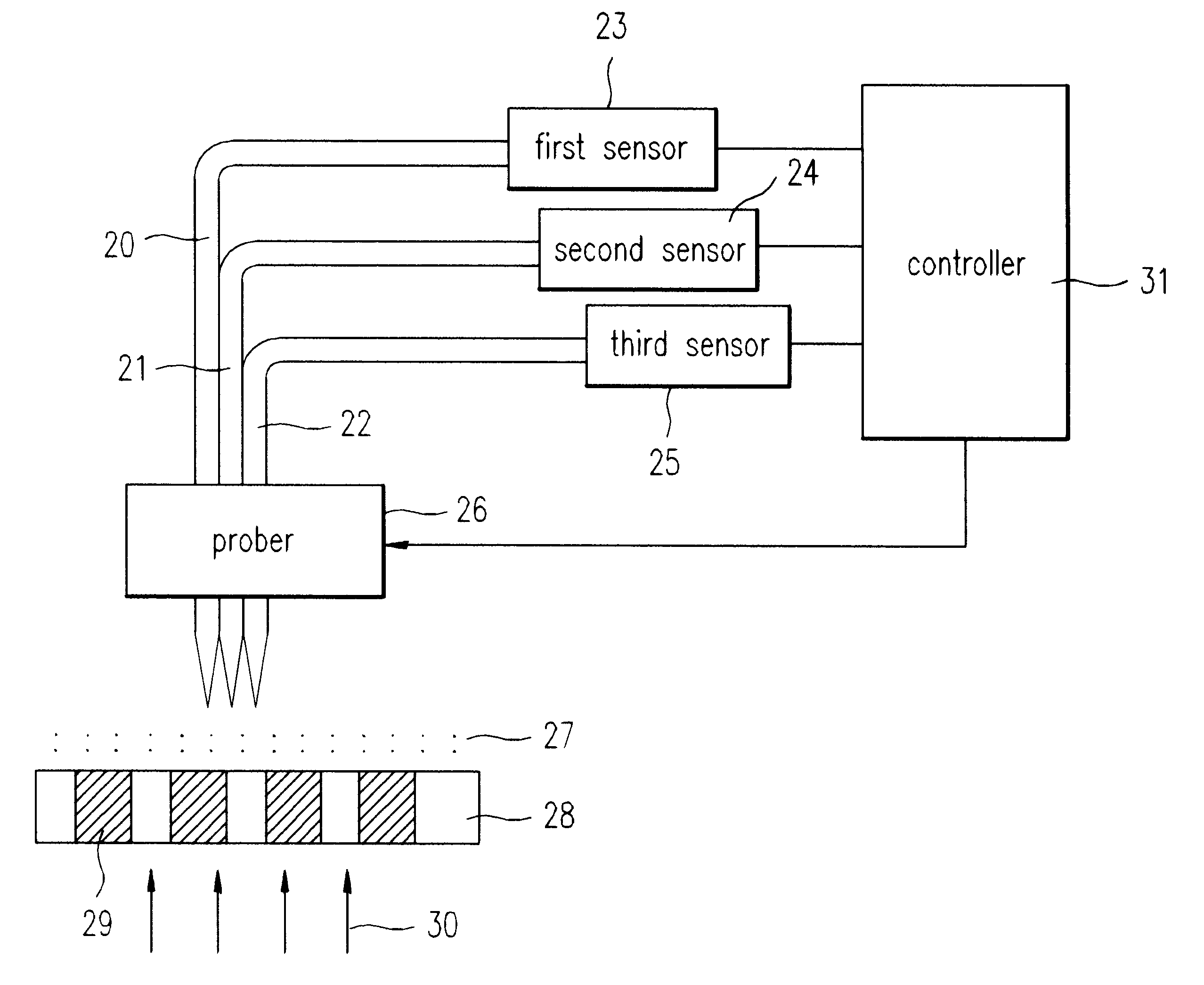
FIG. 4 shows a tracking controllable optical storage according to the present invention, and FIG. 5 shows the cross sections of the fiber probe and tracking probe of FIG. 4. Explanations for the same constituent elements as those of the conventional one will be omitted. Referring to FIG. 4, the optical storage of the invention includes a recording medium 28 on which information is recorded in the form of data marks 29, an optical source 30 from which rays of light are projected to recording medium 28 to create distribution 27 of intensity of radiation corresponding to data marks 29, a fiber probe 21 for reading the information recorded on recording medium 28, two tracking probes 20 and 22, attached to both sides of fiber probe 21, for generating tracking signals to a controller 31, a probe driver 26, attached to fiber probe 21 and...


PUM

PropertyMeasurementUnit
diameter d1aaaaaaaaaa
angle differenceaaaaaaaaaa
conical shapeaaaaaaaaaa

Abstract

An optical storage apparatus, using the near field optical effect, performs tracking along a track of a recording medium to reproduce information recorded on the recording medium without error. The optical storage apparatus includes a first probe to read information recorded on the recording medium and at least two to judge if the track direction of the recording medium is in accordance with the information scanning direction of the first probe. The apparatus also includes a probe actuator to adjust the tracking direction of the first and second probes using a tracking control signal, and a number of sensors to sense the intensity of radiation probed by the first and second probes and to generate tracking signals corresponding to the sensed radiation. The apparatus also includes a controller to generate a tracking control signal using the tracking signals, and to provide the tracking control signal to the probe actuator.

Description

1. Field of the InventionThe present invention relates to optical storage, specifically, to an optical storage using near field optical effect, to which tracking control function is added, and tracking control method using the optical storage.2. Discussion of Related ArtAn optical recording medium such as a CD-ROM focuses incident rays using an object lens, to form an optical spot. This optical spot is projected on data marks recorded on a recording medium, to read optical information recorded thereon. It is impossible for the optical spot to be smaller than the wavelength of the incident rays because of optical diffraction effect. Accordingly, in case of the incident rays having 780 nm of wavelength, the minimum size of the data mark which is able to be recorded and reproduced becomes 780 nm, reaching the limit of recording density. To overcome the limit, an optical storage using the principle of near field scanning microscope is currently being developed. FIG. 1 shows the configur...

Claims


Application Information

Patent Timeline
Patent Type & Authority Patents(United States)
IPC IPC(8): G11B7/09G11B7/135G11B7/125G11B7/08G01Q60/22G01Q80/00
CPCG11B7/0903G11B7/1384B82Y10/00B82Y20/00G01Q80/00G11B7/08
Inventor NOH, SUNG WOO
Owner LG ELECTRONICS INC
Why Eureka
Try Eureka