Ophthalmic imaging apparatus and system

a technology of ophthalmic imaging and equipment, applied in the field of ophthalmic imaging equipment and system, can solve the problems of requiring specialist equipment that is generally bulky, expensive and difficult to transport, and devoted to desk mounted units with significant system complexity and cost, and achieves the effect of reducing the number of patients, reducing the number of procedures, and improving the quality of car

Active Publication Date: 2022-11-03
INTEGRAL SCOPES PTY LTD
View PDF5 Cites 0 Cited by
  • Summary
  • Abstract
  • Description
  • Claims
  • Application Information

AI Technical Summary

Benefits of technology

The invention is a lens system that can produce images of the fundus that have minimal glare and are of the same size and separation regardless of the field angle. The lens system includes an aperture stop and a relay lens positioned in between the objective lens and a microlens array. The aperture stop is positioned in a spaced relationship relative to the relay lens, at a distance that matches the focal length of the relay lens. The system can also include a processing module that uses one or more processors and memory to process the elemental images by selecting separate regions and ignoring certain portions to obtain a sub-set of images that are stitched together to create a processed image of the fundus.

Problems solved by technology

Taking a high quality image of the retina suitable for accurate diagnosis requires specialist equipment that is generally bulky, expensive and difficult to transport.
Currently available retinal imaging instruments such as digital fundus cameras or OCT units are often large, desk mounted units with significant system complexity and cost devoted to the problem of maintaining reliable imaging conditions, particularly the correct distance of the camera optics to the patient's eyeball and stable eye fixation to properly align the patient's line of sight to that of the camera.
If either of these conditions are not met, the resulting image can be out of focus, obscured by flash light glare or exhibit other optical artefacts that reduce the fidelity of the image or obscure significant retinal details.
These instruments are typically not easily portable due to their size and complexity.

Method used


Image

  • Ophthalmic imaging apparatus and system
  • Ophthalmic imaging apparatus and system
  • Ophthalmic imaging apparatus and system

Examples


Embodiment Construction

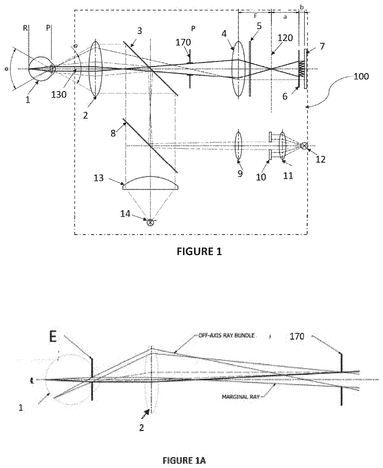
[0070]Referring to FIG. 1, a schematic diagram of an ophthalmic imaging apparatus 100 is illustrated. The ophthalmic imaging apparatus 100 is provided for capturing a plurality of images of the fundus of a subject's eye 1 in a single view. The term “fundus” refers to a posterior pole of the eyeball and generally comprises the retina, the macula and the optic nerve.

[0071]A typical fundus image acquisition method involving the use of the apparatus 100 involves guiding the eye (1) to the correct axial alignment by the use of a fixation assembly that comprises a fixation target (10) whose image is formed at the retinal plane (R). The fixation target is rear illuminated by a low power LED (12) collimated by a lens (11) and its image focussed by lens (9) through a plate beam splitter (8) to a plane, one focal length to the rear of the objective lens (2). This is then projected by the objective lens (2) and as a result, the fixation target (10) is imaged by the eye. To the eye, the fixatio...


PUM


Abstract

An ophthalmic imaging apparatus comprising: an illumination light source and an optical assembly for directing light from the light source into an eye of a subject; a photosensor array comprising a plurality of photosensors positioned for acquiring images of portions of a fundus of the eye; an objective lens positioned along an imaging axis intersecting a point on the fundus of the eye wherein the objective lens is positioned for refracting light that has been reflected by the fundus to form an image of the fund us on an image plane of the objective lens such that the image plane is positioned away from the photosensor array; and a microlens array comprising a plurality of microlenses wherein the microlens array is spaced away from and positioned behind the image plane and wherein the microlens array is positioned in between the image plane and the photosensor array such that each microlens in the array projects a different view of the image formed at the image plane thereby forming an array of elemental images on the photosensor array.

Description

TECHNICAL FIELD[0001]The present invention relates to an ophthalmic imaging apparatus and system particularly for imaging the fundus of a human eye. The invention also relates to a method of ophthalmic imaging.BACKGROUND[0002]Any references to methods, apparatus or documents of the prior art are not to be taken as constituting any evidence or admission that they formed, or form part of the common general knowledge.[0003]Millions of people all over the world suffer from retinal diseases and as a result of lifestyle changes including increased longevity, this number is increasing. Many diseases can result in partial or total blindness but can be treated effectively if diagnosed early and continuously monitored. Taking a high quality image of the retina suitable for accurate diagnosis requires specialist equipment that is generally bulky, expensive and difficult to transport.[0004]The Retinal Plenoptoscope has been designed to provide wide field images and retinal topography suitable f...

Claims


Application Information

Patent Timeline
Patent Type & Authority Applications(United States)
IPC IPC(8): A61B3/12A61B3/00A61B3/14
CPCA61B3/12A61B3/0025A61B3/14
Inventor JAIPRAKASH, ANJALIPALMER, DOUGLASDANSEREAU, DONALD GILBERTCOPPIN, THOMASRANA, KRISHANROBERTS, JONATHANCRAWFORD, ROSS
Owner INTEGRAL SCOPES PTY LTD
Why Eureka
Try Eureka