
Hydrogen-filling hose

a technology of hydrogen-filled hoses and hoses, which is applied in the direction of mechanical equipment, other domestic objects, synthetic resin layered products, etc., can solve the problems of metal wire material easily clogging with hydrogen, and achieve the effect of increasing the flow rate of high-pressure hydrogen gas, and ensuring the safety of metal wires

Active Publication Date: 2022-10-13
THE YOKOHAMA RUBBER CO LTD
View PDF6 Cites 0 Cited by
  • Summary
  • Abstract
  • Description
  • Claims
  • Application Information

AI Technical Summary

Benefits of technology

The present invention is about a new type of hose that can handle high-pressure hydrogen gas. The hose has a large diameter flow path of 10 mm or more and 25 mm or less, which increases the flow rate of the gas. The hose has multiple reinforcing layers that are formed in a spiral structure, which helps it withstand high pressure. The hose also has pricking holes dispersed on its outer surface, which allows the hydrogen gas to flow out smoothly and easily. This prevents the gas from embrittling the metal wire material.

Problems solved by technology

Accordingly, when the reinforcing layer is formed of a metal wire material, the metal wire material may easily embrittle by hydrogen.

Method used


Image

  • Hydrogen-filling hose
  • Hydrogen-filling hose

Examples


Embodiment Construction

[0012]A hydrogen-filling hose according to the present invention will be described below based on embodiments illustrated in the drawings.

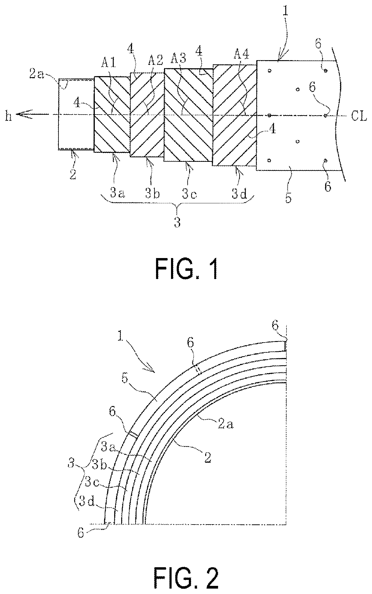
[0013]As illustrated in FIGS. 1 and 2, a hydrogen-filling hose 1 (hereafter referred to as a hose 1) according to an embodiment of the present invention is configured such that an inner surface layer 2, reinforcing layers 3 (3a, 3b, 3c, 3d), and an outer surface layer 5 are coaxially layered in the order from the inner circumferential side thereof. Note that a dot-dash line CL in the drawings represents a hose axis.

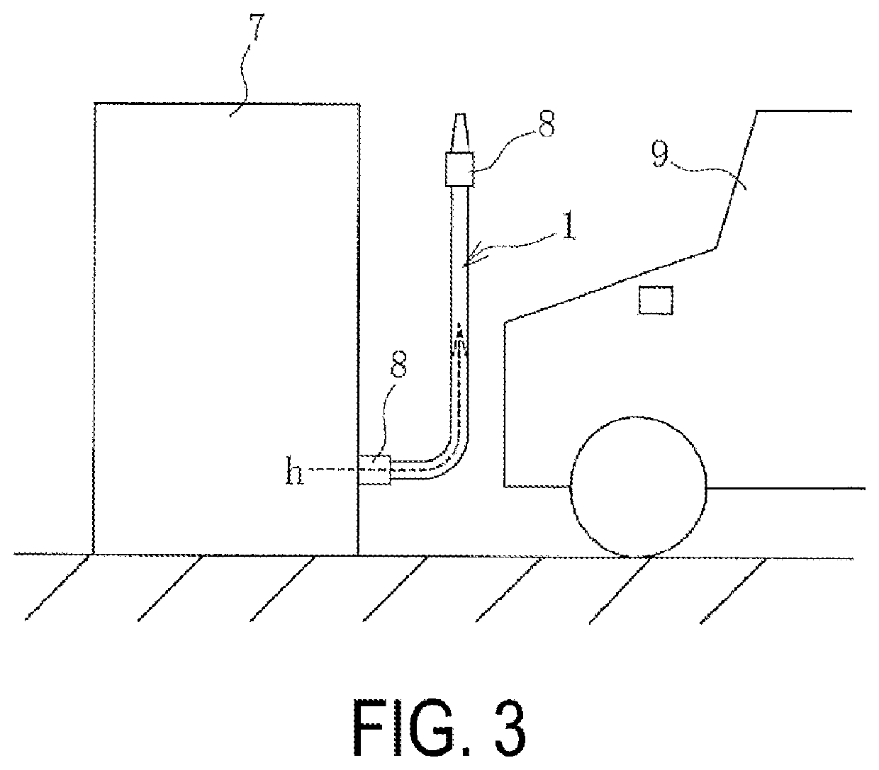
[0014]As illustrated in FIG. 3, when the hose 1 is equipped on a dispenser 7 installed at a hydrogen station, hose fittings 8 are crimped and attached to both ends of the hose 1. Hydrogen gas h at a low temperature (for example, −40° C. or more and −20° C. or less) and high pressure (for example, 70 MPa or more and 87.5 MPa or less) is supplied and fed from the dispenser 7 through the hose 1 to a vehicle 9, a storage tank, or the like. ...


PUM

PropertyMeasurementUnit
diameteraaaaaaaaaa
diameteraaaaaaaaaa
temperatureaaaaaaaaaa

Abstract

A hydrogen-filling hose includes reinforcing layers provided coaxially layered between an inner surface layer and an outer surface layer that are coaxially layered. The inner surface layer is formed of a thermoplastic resin and has a gas permeation coefficient of dry hydrogen gas, of 1×10⁻⁸ cc⋅cm / cm2⋅sec.⋅cmHg or less at 90° C. A flow path formed by the inner surface layer has a diameter of 10 mm or more and 25 mm or less. The reinforcing layers includes four layers or more and eight layers or less, and each of the reinforcing layers has a spiral structure that is formed by spirally winding a metal wire material. Pricking holes extending through the outer surface layer in a thickness direction are dispersedly provided therein.

Description

TECHNICAL FIELD[0001]The present invention relates to a hydrogen-filling hose and particularly relates to a hydrogen-filling hose capable of feeding high-pressure hydrogen gas at a larger flow rate.BACKGROUND ART[0002]Various hoses that feed hydrogen gas to fuel cell vehicles or the like have been proposed (for example, see Patent Document 1). A hydrogen-filling hose has been demanded not only to have superior hydrogen gas permeation resistance but also, in recent years, to supply a larger amount of hydrogen gas in a shorter time from a dispenser to fuel cell vehicles or the like.[0003]When the inner diameter of the hose is simply increased to meet such a demand and the flow rate of high-pressure hydrogen gas is increased, burst pressure of the hose decreases. Consequently, pressure resistance performance of the hose needs to be improved. Forming a reinforcing layer of the hose from a metal wire material is more advantageous than forming that from fibers in reliably transferring for...

Claims


Application Information

Patent Timeline
Patent Type & Authority Applications(United States)
IPC IPC(8): F16L11/08F16L11/12
CPCF16L11/083F16L11/12F16L11/08Y02E60/32F16L2011/047B32B25/14B32B15/02B32B27/40B32B3/18B32B15/08B32B7/02B32B2605/00B32B1/08B32B3/266B32B15/06B32B25/18B32B27/36B32B2597/00B32B25/16B32B2307/732B32B2307/724B32B2307/712B32B15/043
Inventor YUSA, IKUMA
Owner THE YOKOHAMA RUBBER CO LTD
Learn More