Interproximal Reduction Tool And Method

a technology of proximal and proximal discs, applied in the field of dental surgery, can solve the problems of creating various problems, reducing the accuracy of proximal cutting, so as to reduce the risk, reduce the risk, and reduce the effect of high torqu

Pending Publication Date: 2022-08-25
GALLER DAVID +1
View PDF4 Cites 1 Cited by
  • Summary
  • Abstract
  • Description
  • Claims
  • Application Information

AI Technical Summary

Benefits of technology

[0006]The present invention provides an interproximal reduction tool and method, which greatly reduces the risk creating a gouged out area between two adjacent teeth. The interproximal reduction tool and method preferably includes at least one polishing strip; at least one abrasive wheel; and a low speed and high torque dental electric motor. First, the area between two adjacent teeth is manually polished with a plurality of polishing strips to create a 0.09 mm space between the two adjacent teeth. A preferred polishing strip is sold under the name of Qwik Strips. The polishing strips come in increasing values of thickness. The polishing strips have single sided grit and come in yellow, red, blue, green and black sizes. The polishing strip is held between a forefinger and thumb. The polishing strip is moved in a horizontal plane, until a 0.09 mm space is created between two adjacent teeth. However, other types of dental abrasive strips may also be used.
[0007]Each abrasive wheel preferably includes an abrasive disk and a shaft. The abrasive wheel is mounted to one end of the shaft. However, an abrasive wheel could be secured to an end of a motorshaft. The abrasive wheel includes a disc base and abrasive material. The abrasive material is adhered to opposing sides of the disc base. An annular shape of abrasive material is formed onopposing sides of the disc base. It is preferable to have an annular space between an outer edge of the disc base and an outer perimeter of the annular abrasive material to prevent gouging to adjacent teeth. It is critical to prevent the abrasive disc from “end cutting,” which can cut into the enamel of a tooth instead of just reducing the outside layer of the tooth on the interproximal surface. The annular space on the abrasive disc prevents the “end cutting” of the tooth. It is preferable to have a second annular space without abrasive between an inside perimeter of the abrasivematerial and the shaft. The second annular space prevents accidental destruction of the adjacent tooth.
[0008]The abrasive discs preferably come in a thickness of yellow (0.15 mm) red (0.20 mm) blue (0.30 mm), green (0.40 mm) and black (0.50). It is preferable that the grit be sourced from Strauss Diamond. The low speed / high torque motor preferably utilizes an existing dental motor, such as a Marathon III micro motor, and modifies the dental motor to have a preferable gear reduction of 16:1 to reduce speed by 1 / 16 and increase torque 16 times. The gear reduction results in a slower rotation of the abrasive disc to provide extreme precision; improved tactile control to the dentist; and prevents the disc from getting caught between the two adjacent teeth.
[0009]Accordingly, it is an object of the present invention to provide an interproximal reduction tool and method, which greatly reduces the risk of creating “end cutting” between two adjacent teeth, when trying to form a space between the two adjacent teeth that are in contact with each other.
[0010]It is another object of the present invention to provide aninterproximal reduction tool and method, which provides color coordination to alleviate the need for guesstimating by eye or using a Womack gauge to measure a distance between two adjacent teeth.
[0011]Finally, it is object of the present invention to provide an interproximal reduction tool and method, which includes differing sequential increasing grits of an abrasive disc and thicknesses of polishing strips that provide a practitioner with much better tactile control to provide a more precise space between two adjacent teeth.

Problems solved by technology

Each of these methods creates various problems.
The above procedure is time consuming and very inexact.
The Kuo tool has the disadvantage of having the abrasive material all the way to an edge of the disc.
Having abrasive material on the edge of the material will frequently result in an unwanted gouged out area between the teeth.

Method used


Image

  • Interproximal Reduction Tool And Method
  • Interproximal Reduction Tool And Method
  • Interproximal Reduction Tool And Method

Examples


Embodiment Construction

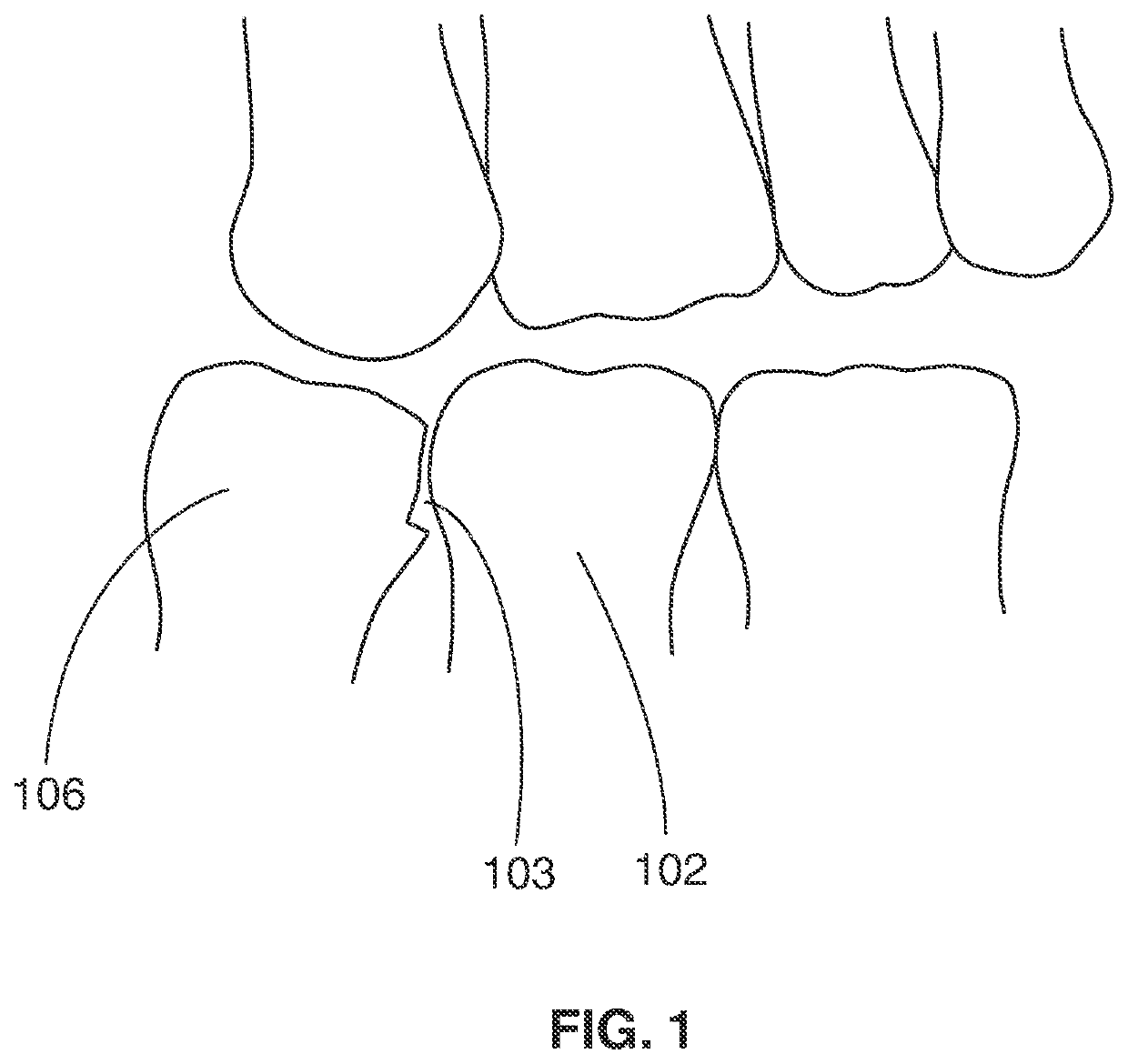
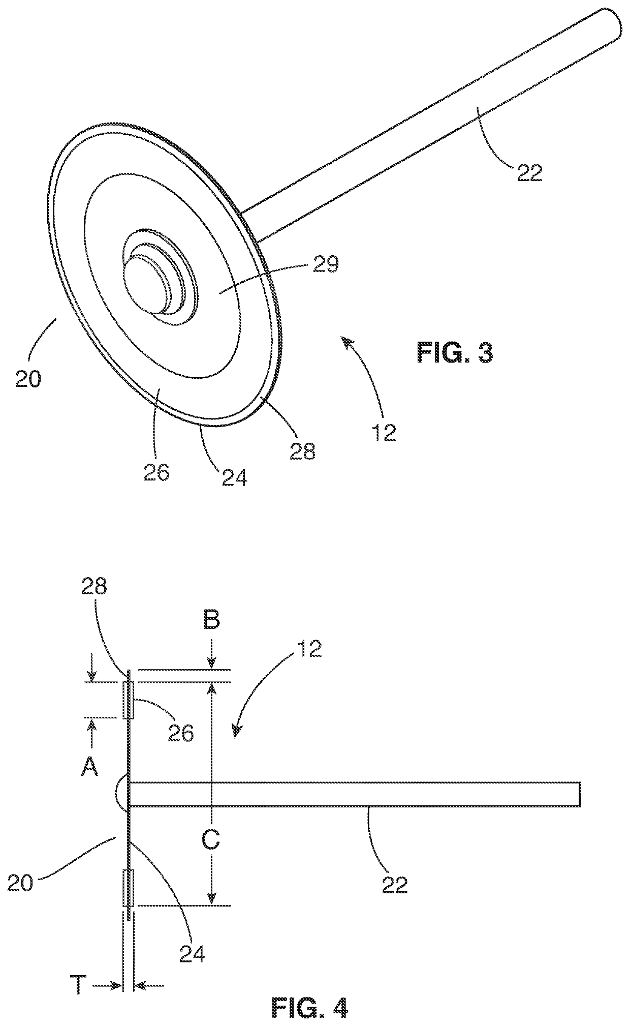
[0020]With reference now to the drawings, and particularly to FIG. 2, there is shown a perspective view of a dental polishing strip 10. FIG. 1 illustrates an end cut 103, which created by a prior art abrasive wheel between two adjacent teeth. The end cut 103 removed a significant portion of tooth enamel of the tooth 100. With reference to FIGS. 3-5, the interproximal reduction tool and method preferably includes at least one polishing strip 10; at least one abrasive wheel 12; and a low speed and high torque dental electric motor 14. First, the area between two adjacent teeth 100, 102 is manually polished with the thinnest polishing strip 10. A preferred polishing strip is sold under the name of Qwik Strips. The polishing strips come in increasing values of thickness. The polishing strips have single sided grit and come in yellow, red, blue, green and black. Each polishing strip 10 includes a polishing member 16 and a holder 18. The polishing strip 10 is held between a forefinger and...


PUM


Abstract

An interproximal reduction tool and method preferably includes at least one polishing strip; at least one abrasive wheel; and a low speed and high torque dental electric motor. First, the area between two adjacent teeth is manually polished with a plurality of polishing strips. The polishing strip is held between a forefinger and thumb and moved in a horizontal plane. Each abrasive wheel preferably includes an abrasive disc and a shaft. The abrasive disc includes a disc base and abrasive material. The abrasive material is adhered to opposing sides of the disc base. It is preferable to have an annular space between an outer edge of the disc base and an outer perimeter of the annular abrasive material. The low speed / high torque motor preferably utilizes an existing dental motor and modifies the dental motor to have a preferable gear reduction of at least 16:1.

Description

CROSS-REFERENCE TO RELATED APPLICATION[0001]This application is a continuation of U.S. application Ser. No. 17 / 089,080, filed Nov. 4, 2020, the contents of which are hereby incorporated by reference.BACKGROUND OF THE INVENTION1. Field of the Invention[0002]The present invention relates generally to dentistry and more specifically to an interproximal reduction tool and method, which enables a space to be created between adjacent teeth that are in contact with each other.2. Discussion of the Prior Art[0003]Interproximal reduction is a procedure used in Orthodontics to create a space between two adjacent teeth to allow for Orthodontic Movement between the two adjacent teeth. Creation of a space between two adjacent teeth has traditionally been done with burs, regular discs or finishing strips. Each of these methods creates various problems. Further, space created between two adjacent teeth needs to be estimated by eye or by using a separate metal gauge known as the Womack Gauge. (https...

Claims


Application Information

Patent Timeline
Patent Type & Authority Applications(United States)
IPC IPC(8): A61C1/06A61C1/08A61C1/14
CPCA61C1/06A61C1/082A61C1/145A61C3/06A61C3/12A61C1/10A61C1/16
Inventor GALLER, DAVIDOSTREICHER, DAVID
Owner GALLER DAVID
Why Eureka
Try Eureka