Motor, motor state detection device, and motor state determination device
- Summary
- Abstract
- Description
- Claims
- Application Information
AI Technical Summary
Benefits of technology
Problems solved by technology
Method used
Image

Examples
first embodiment
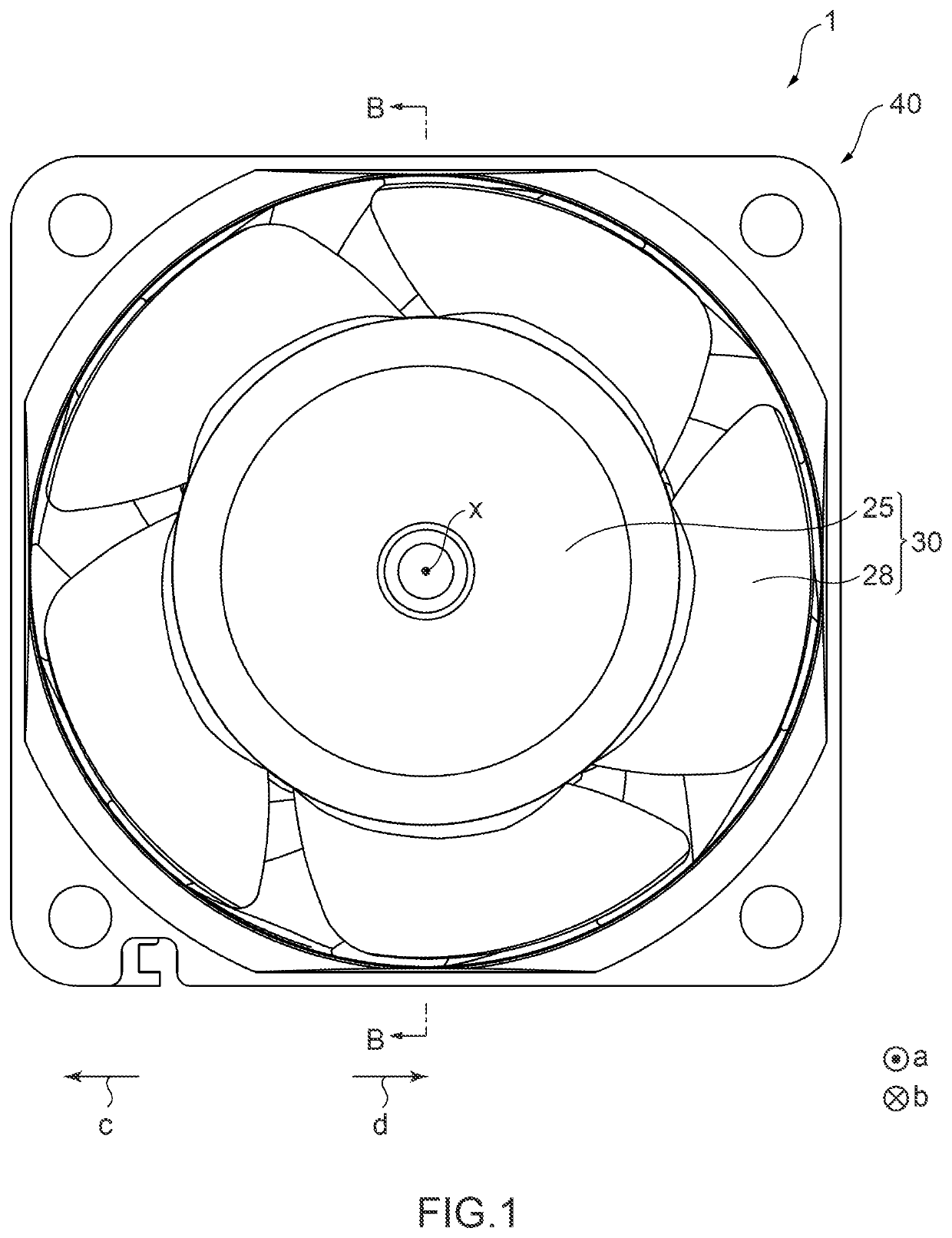
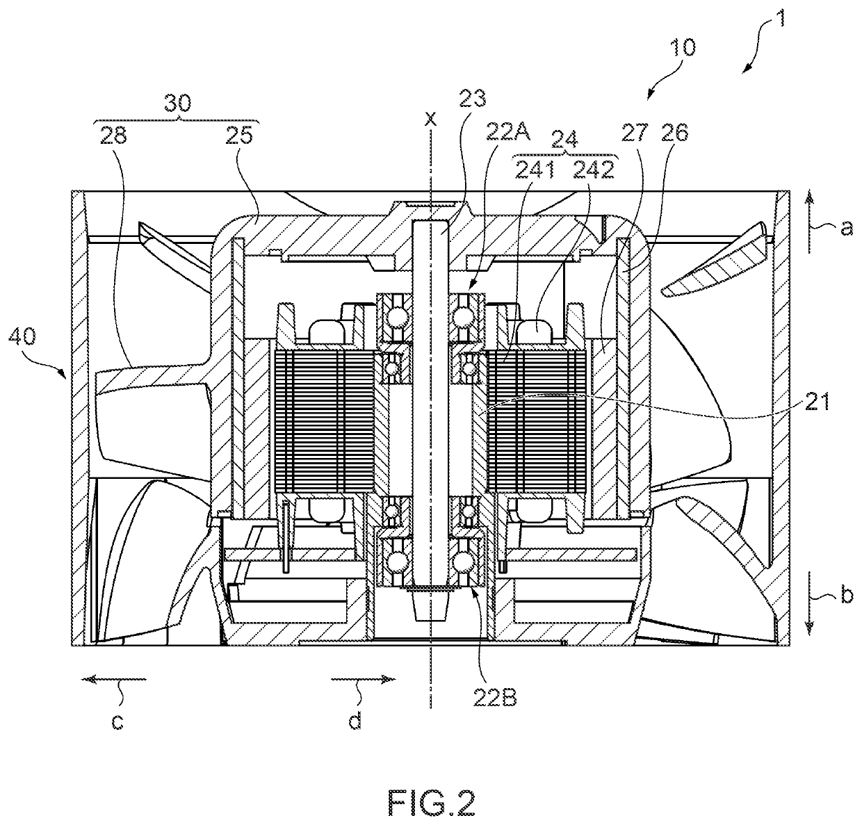
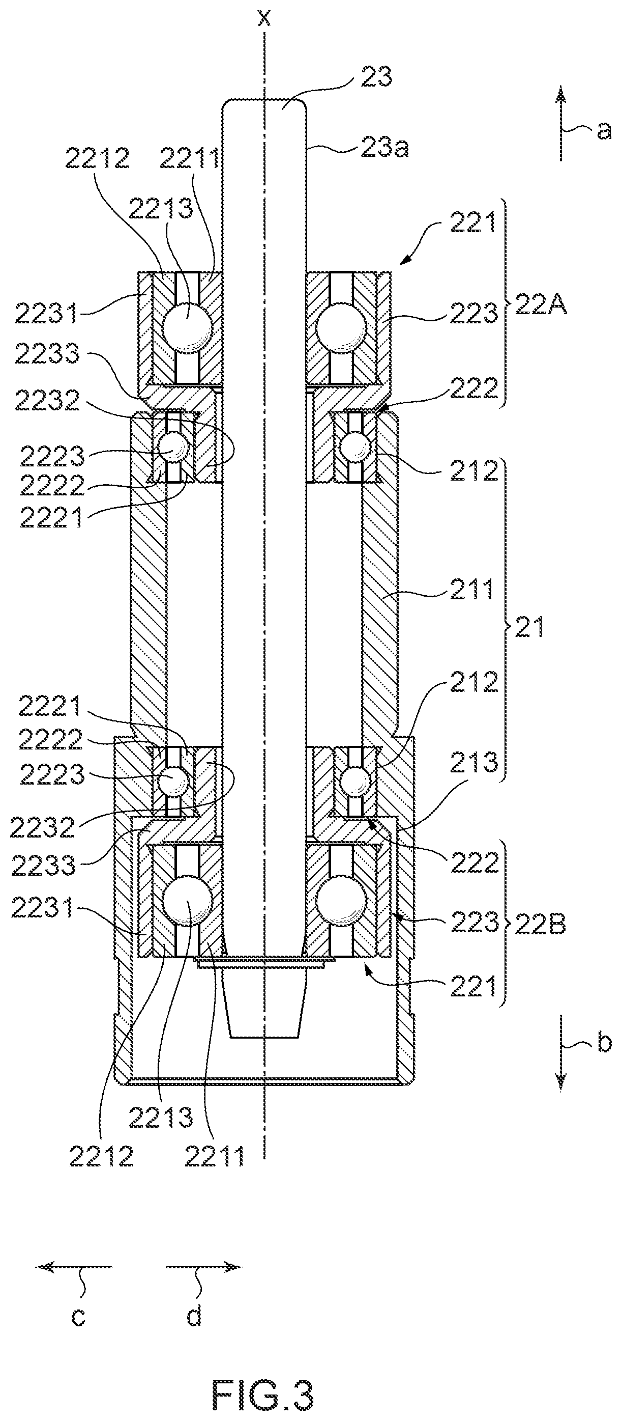
[0068]FIG. 1 is a front view schematically showing configuration of a fan device 1 including a motor 10 of a first embodiment according to the present invention. FIG. 2 is a sectional view schematically showing configuration of the fan device 1. FIG. 3 is a sectional view schematically showing configuration of a rotation shaft 23 and bearing portions 22 included in the fan device 1.
[0069]In the following description, for convenience, it is assumed that the direction of arrow a in the axial line x direction is an upper side a and the direction of arrow b is a lower side b. It is also assumed that a direction away from the axial line x in the radial direction perpendicular to the axial line x (the direction of arrow c in FIG. 1) is an outer periphery side c and a direction toward the axial line x (the direction of arrow d in FIG. 1) is an inner periphery side d. In the following description, for convenience, it is assumed that the direction indicated in FIG. 1 is toward a side surface...
second embodiment
[0115]Next, a motor according to the present invention will be described. Note that components of the motor according to the present embodiment similar to those of the motor 10 previously described are given by the same reference characters, and descriptions of these components will be omitted.
[0116]FIG. 9 is a sectional view schematically showing configuration of the rotation shaft 23 and bearing portions 22Ab and 22Bb included in the motor according to the second embodiment of the present invention.
[0117]As shown in FIG. 9, in the pair of bearing portions 22Ab and 22Bb included in the motor according to the second embodiment, in a manner similar to the pair of bearing portions 22A and 22B previously described, the bearing portion 22Ab is supported by a bearing supporting portion 212b provided at one end of a bearing housing 21b in the axial line x direction, and the bearing portion 22Bb is supported by a bearing supporting portion 213b provided at another end of the bearing housin...
third embodiment
[0122]Next, a fan device 1C including a motor 10C of a third embodiment according to the present invention will be described. Note that components of the motor 10C according to the present embodiment similar to those of the motor 10 previously described are given by the same reference characters, and descriptions of these components will be omitted.
[0123]FIG. 10 is a sectional view schematically showing configuration of the fan device 1C. FIG. 11 is a front view schematically showing configuration of the motor 10C. FIG. 12 is a sectional view schematically showing configuration of the motor 10C. FIG. 13 is a sectional view schematically showing configuration of a rotation shaft 23C and bearing portions 22AC and 22BC included in the fan device 1C.
[0124]As shown in FIGS. 10 to 13, the motor 10C according to the present embodiment is provided to the fan device 1C and includes a rotor having a rotation shaft 23C, a stator 24C arranged oppositely in the circumferential direction of the r...
PUM
 Abstract
Description
Claims
Application Information
 - R&D
- Intellectual Property
- Life Sciences
- Materials
- Tech Scout
- Unparalleled Data Quality
- Higher Quality Content
- 60% Fewer Hallucinations
Browse by: Latest US Patents, China's latest patents, Technical Efficacy Thesaurus, Application Domain, Technology Topic, Popular Technical Reports.
© 2025 PatSnap. All rights reserved.Legal|Privacy policy|Modern Slavery Act Transparency Statement|Sitemap|About US| Contact US: help@patsnap.com