
Dg intentional islanding using padmount transformer interrupters

a transformer interrupter and padmount technology, applied in the direction of system intergating technology, emergency protective circuit arrangement, ac network circuit arrangement, etc., can solve problems such as potential safety issues and voltage that exceeds the maximum voltage that the utility is required to regula

Pending Publication Date: 2022-05-19
S&C ELECTRIC
View PDF0 Cites 0 Cited by
  • Summary
  • Abstract
  • Description
  • Claims
  • Application Information

AI Technical Summary

Benefits of technology

The patent describes a system and method for maintaining power in an underground power distribution network when there is a loss of power. The system includes a power line and multiple transformers along the power line, each connected to a section of the network with loads. The method allows distributed power sources to provide power to the section when there is a loss of voltage. The system also allows excess power from one section to be shared with an adjacent section, while ensuring that there is no excess power in the section that is not experiencing a loss of power. Overall, the system is able to optimize power distribution and minimize downtime in the event of a power loss.

Problems solved by technology

This is important because if a utility worker is dispatched to the loop circuit for service or repair, that person may not know that power is being injected onto the circuit by the distributed power sources, thus creating a possible safety issue.
Exporting power across a transformer causes an increase in voltage experienced by other customers being serviced by the same transformer, which can result in voltage that exceeds the maximum voltage that the utility is required to regulate.

Method used


Image

  • Dg intentional islanding using padmount transformer interrupters
  • Dg intentional islanding using padmount transformer interrupters
  • Dg intentional islanding using padmount transformer interrupters

Examples


Embodiment Construction

[0011]The following discussion of the embodiments of the disclosure directed to a system and method for allowing islanding in an underground power distribution network when power is lost to the network is merely exemplary in nature, and is in no way intended to limit the invention or its applications or uses. For example, as mentioned, the system and method have particular application for use in a residential loop circuit. However, the system and method may have other applications.

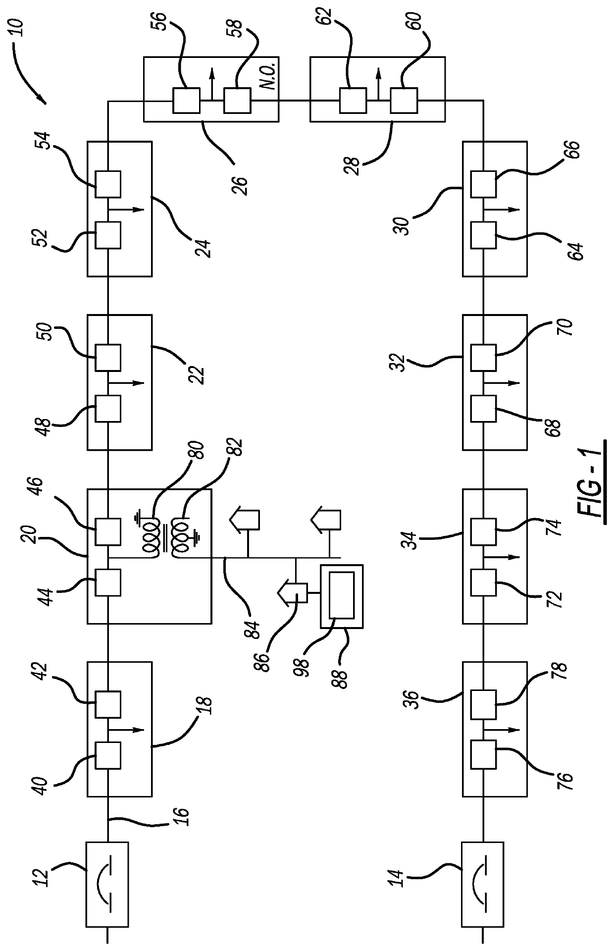
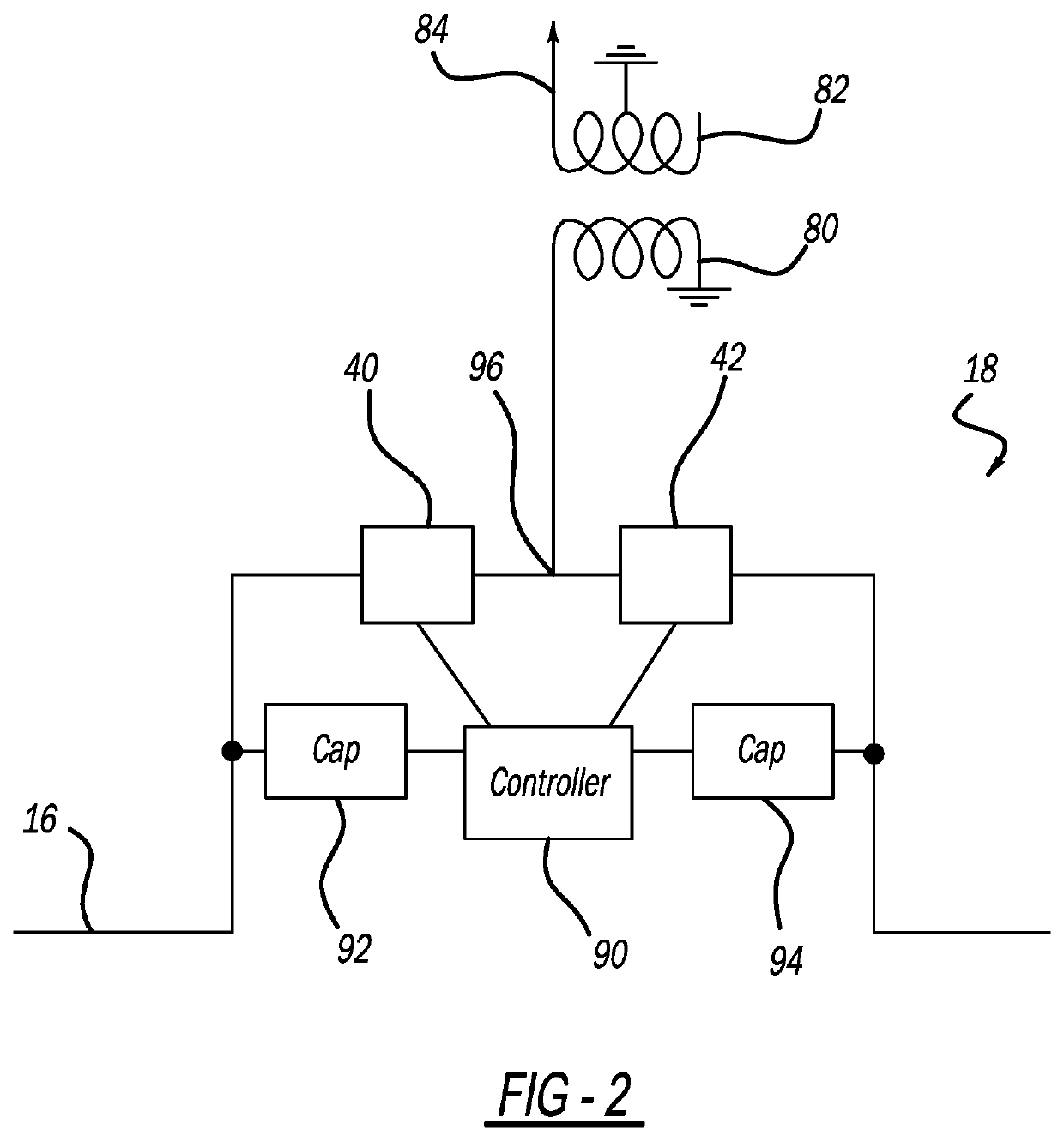
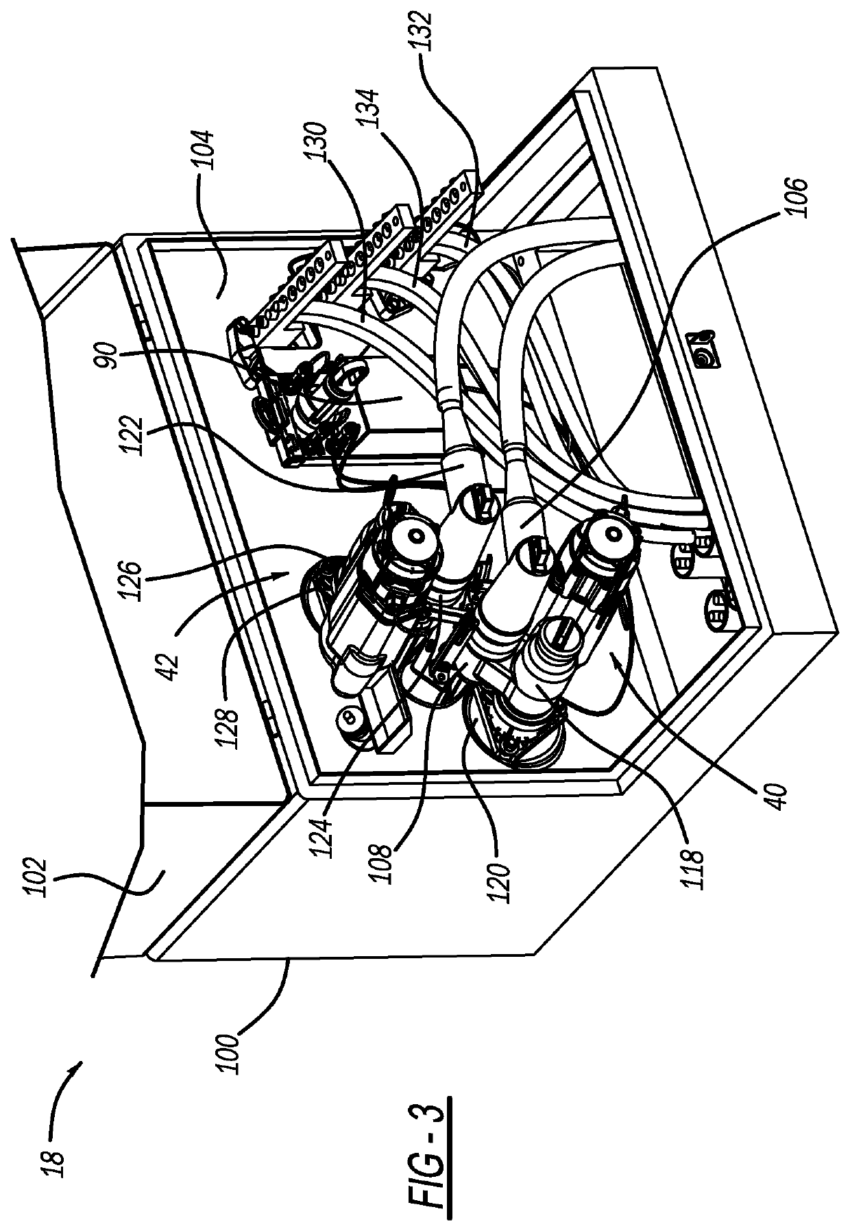
[0012]FIG. 1 is a simplified schematic diagram of an underground power distribution network 10 that is fed power from both ends. The network 10 includes, for example, two single-phase, self-powered, magnetically actuated reclosers 12 and 14 connected to the same or different feeders (not shown), or other source of power, at the head ends of the network 10, an underground distribution power line 16 and ten transformers 18, 20, 22, 24, 26, 28, 30, 32, 34 and 36 coupled along the line 16. Each transformer 18,...


PUM


Abstract

A system and method for allowing islanding in an underground power distribution network when power is lost to the network. The network includes transformers having source side and load side switching devices and servicing a transformer section. The method includes detecting loss of voltage to the network, opening the source side and the load side switching devices in all of the transformers and allowing distributed power generation sources in the sections serviced by the transformers to provide power to the section. The method also includes closing one or both of the source side switching device and the load side switching device of a transformer that services a section that has power generation sources providing excess power, and closing a source side switching device or a load side switching device in an adjacent transformer to the transformer section providing excess power to provide power to the adjacent section.

Description

CROSS-REFERENCE TO RELATED APPLICATION[0001]This application claims the benefit of priority from the U.S. Provisional Application No. 63 / 115,821, filed on Nov. 19, 2020, the disclosure of which is hereby expressly incorporated herein by reference for all purposes.BACKGROUNDField[0002]The present disclosure relates generally to a system and method for allowing islanding in an underground power distribution network when power is lost to the network and, more particularly, to a system and method for allowing islanding in an underground power distribution network when power is lost to the network by systematically operating switches at adjacent transformer sections.Discussion of the Related Art[0003]An electrical power distribution network, often referred to as an electrical grid, typically includes a number of power generation plants each having a number of power generators, such as gas turbines, nuclear reactors, coal-fired generators, hydro-electric dams, etc. The power plants provid...

Claims


Application Information

Patent Timeline
IPC IPC(8): H02J3/38
CPCH02J3/388H02H7/26H02J3/381H02J13/00002H02J13/00004Y02E40/70Y02E60/00Y04S10/12Y04S10/20Y04S10/30
Inventor MATAMOROS, JOSEPH
Owner S&C ELECTRIC
Learn More