
Accumulator System Having a High-Voltage Accumulator for Mobile Work Machines

a technology of high-voltage accumulator and work machine, which is applied in secondary cell servicing/maintenance, batteries, instruments, etc., can solve the problems of high risk of short circuit during electrical work, inability to automatically switch off, and additional costs, so as to prolong the maximum operating time, and increase the energy source

Pending Publication Date: 2022-04-28
WACKER NEUSON LINZ
View PDF1 Cites 0 Cited by
  • Summary
  • Abstract
  • Description
  • Claims
  • Application Information

AI Technical Summary

Benefits of technology

This patent is about a new type of accumulator system for vehicles that avoids the shortcomings of existing systems. The system is activated without needing an on-board battery, and can deactivate itself if there are any abnormal requests. It also ensures that the vehicle's electrical system is always ready for use, even in emergency situations. By using a high-voltage accumulator and a standby circuit, the system is much more powerful and can operate for longer periods of time in case of maintenance or failure. Additionally, the system is designed to prevent any short circuits and reduce the risk of injury or fire. The patent suggests using at least two line connections, one for high-voltage and another for low-voltage.

Problems solved by technology

This means that manual intervention is necessary in order to ensure that the battery is not unnecessarily discharged during downtimes. Automatic switch-off is not possible.
Since the on-board battery is electrically directly connected to the vehicle mass, there is always a high risk of a short circuit during electrical work and in the event of a fault owing to the low internal resistance of the on-board battery.
These give rise to additional costs and, as wear parts, must be changed approximately every 4-6 years.
In addition, the on-board battery continuously consumes energy, since it always has to be recharged, and takes up further installation space which is often very limited in small devices, machines and vehicles.
These loads can cause a deep discharge of the battery very quickly to such an extent that it is no longer possible at all to activate the high-voltage accumulator without outside help or without replacing the on-board battery.

Method used


Image

  • Accumulator System Having a High-Voltage Accumulator for Mobile Work Machines
  • Accumulator System Having a High-Voltage Accumulator for Mobile Work Machines
  • Accumulator System Having a High-Voltage Accumulator for Mobile Work Machines

Examples


Embodiment Construction

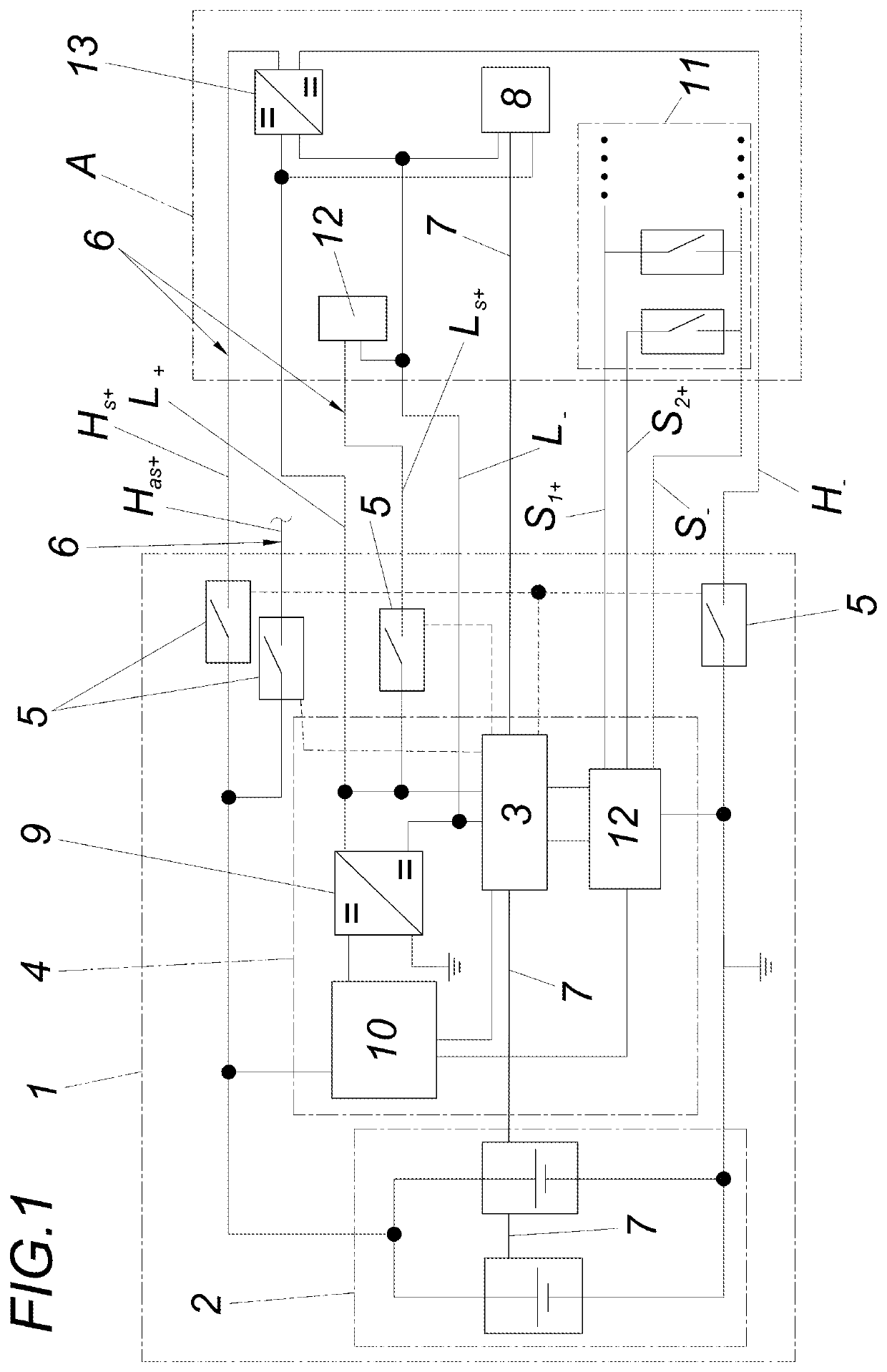
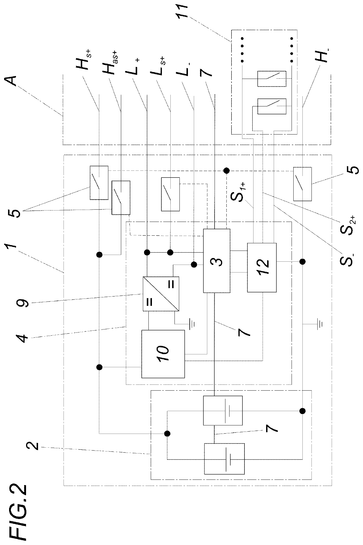
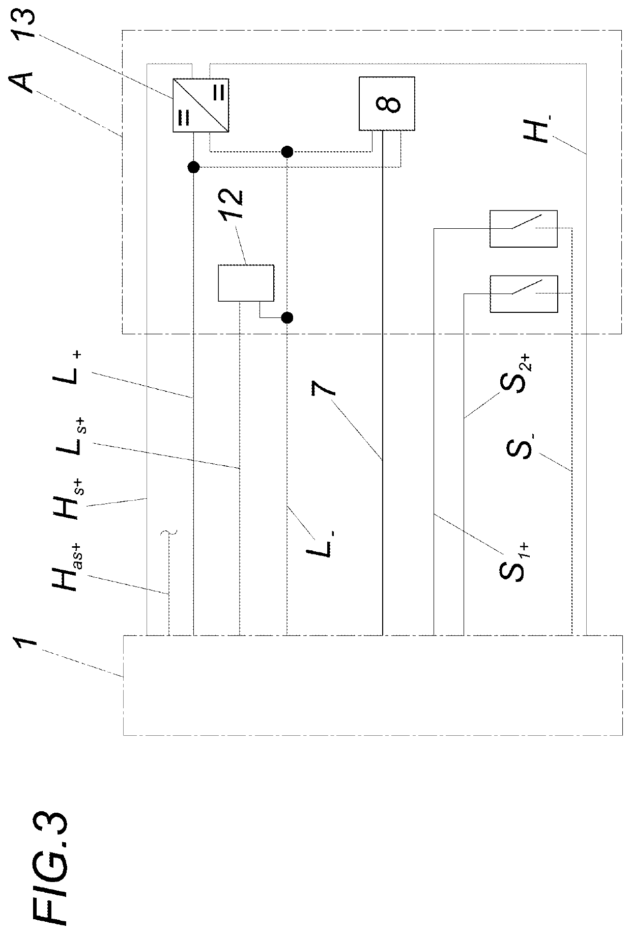
[0028]The accumulator system 1, which can be accommodated by a work machine A, in particular in a replaceable manner, comprises a high-voltage accumulator 2 which provides corresponding drive powers, a battery management system 4 which has a controller 3, line connections 6 which can be switched by means of switches 5, and a data bus 7 for connection to a work machine control system 8.

[0029]According to the invention, the battery management system 4 has, for supplying voltage to the controller 3, a DC / DC converter 9 which is located upstream of the controller 3 and, for the purpose of supplying voltage to the controller 3, is connected to the high-voltage accumulator 2 via a standby circuit 10. The standby circuit 10 can be activated via a circuit 11 outside the accumulator system.

[0030]A safety circuit 12 is integrated in a circuit which, in addition to the high-voltage accumulator 2, comprises at least the standby circuit 10, the controller 3 and the circuit 11 outside the accumul...


PUM

PropertyMeasurementUnit
voltageaaaaaaaaaa
electrical energyaaaaaaaaaa
energyaaaaaaaaaa

Abstract

An accumulator system has a high-voltage accumulator for mobile work machines. A battery management system, has a controller-line connections which can be switched by switches; and a data bus for connection to a work machine control unit. In order to advantageously render an electrical-system battery unnecessary, the battery management system comprises, for voltage supply, a DC-DC converter which is located upstream of the controller in terms of current flow and which is connected to the high-voltage accumulator via a standby circuit. The standby circuit can be activated by means of a circuit that is external to the accumulator system.

Description

FIELD OF THE INVENTION[0001]The invention relates to an accumulator system having a high-voltage accumulator for mobile work machines, comprising a battery management system which has a controller, line connections which can be switched by means of switches, and a data bus for connection to a work machine control system.BACKGROUND OF THE INVENTION[0002]If work machines are supplied with electrical energy from a high-power (high-voltage) accumulator, it is known practice to guarantee the 12 / 24 V on-board power supply of the vehicle or of the work machine by means of a separate, external energy store, for example an on-board battery (EP 2 031 135 A1). The external energy store can be recharged by the battery system via a DC / DC converter or via a generator provided in the drive train of the work machine. In the present case, the term “high power” relates to a DC circuit which can be used to transmit drive powers. Said DC circuit need not necessarily carry higher voltages than the vehic...

Claims


Application Information

Patent Timeline
Patent Type & Authority Applications(United States)
IPC IPC(8): H01M10/42B60L15/40B60L58/10B60L3/04B60L3/00H02J9/06H01M10/46
CPCH01M10/425B60L15/40B60L58/10B60L3/04B60L3/0046H01M2200/00H01M10/46B60L2210/10H01M2010/4271H01M2220/20H02J9/06G01R31/382H02J1/082H02J9/005H02J7/0029H02J2310/48H02J2207/10H02J7/0063B60L2200/40Y02T10/70Y02T10/72Y02E60/10
Inventor THUMFART, HARALDRECHEIS, MANESFINZEL, ROBERTERLINGER, THOMASKRÖPL, CHRISTIANLEIBETSEDER, OLIVER
Owner WACKER NEUSON LINZ
Learn More