
Field customizable airflow system for a communications box

a communication box and airflow technology, applied in the field of field customization of airflow systems for communications boxes, can solve problems such as improper operation, equipment failure, undesirable consequences, etc., and achieve the effect of facilitating signal propagation and reception, and facilitating internet connectivity

Active Publication Date: 2022-04-07
MFG RESOURCES INT INC
View PDF0 Cites 3 Cited by
  • Summary
  • Abstract
  • Description
  • Claims
  • Application Information

AI Technical Summary

Benefits of technology

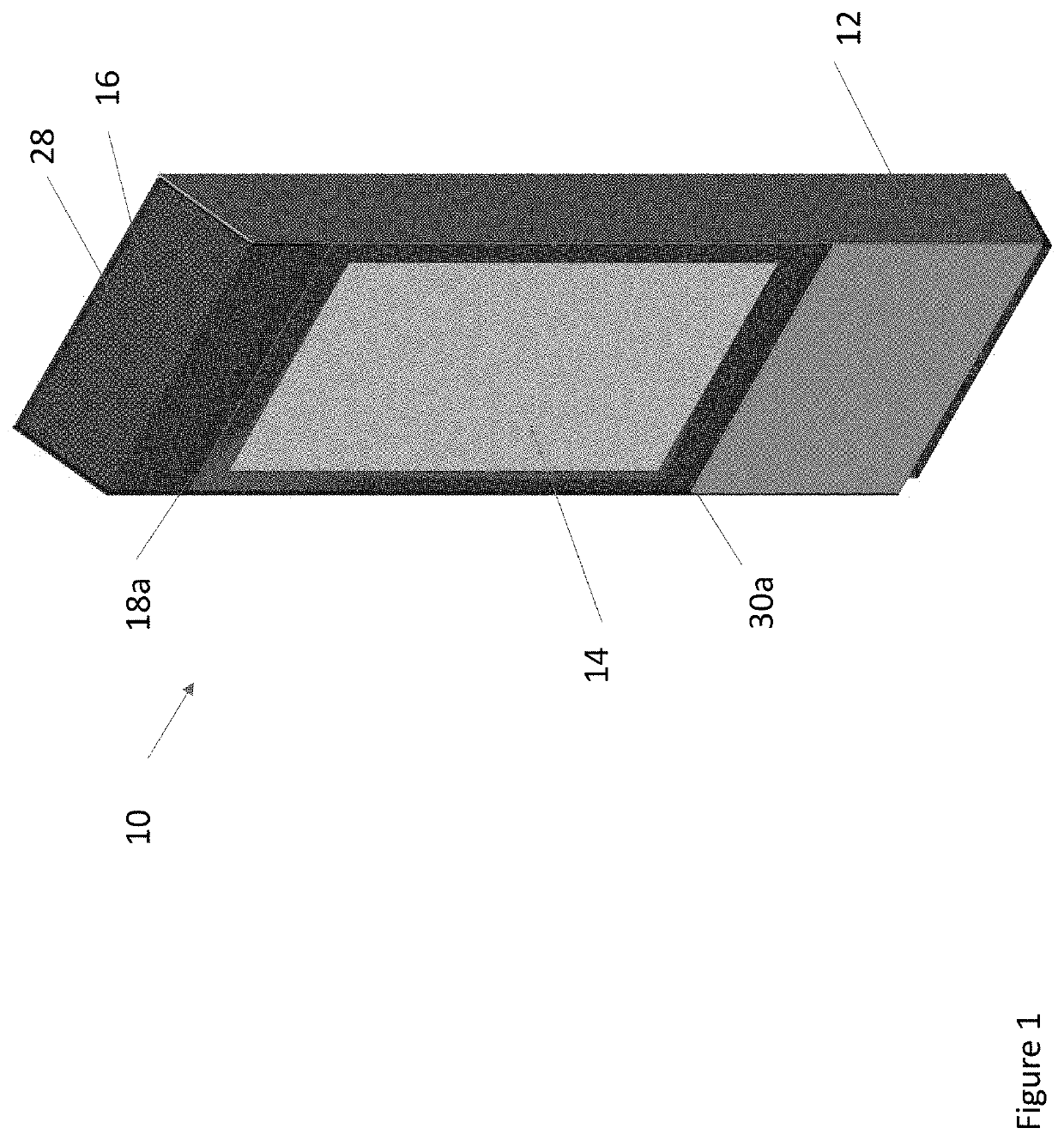
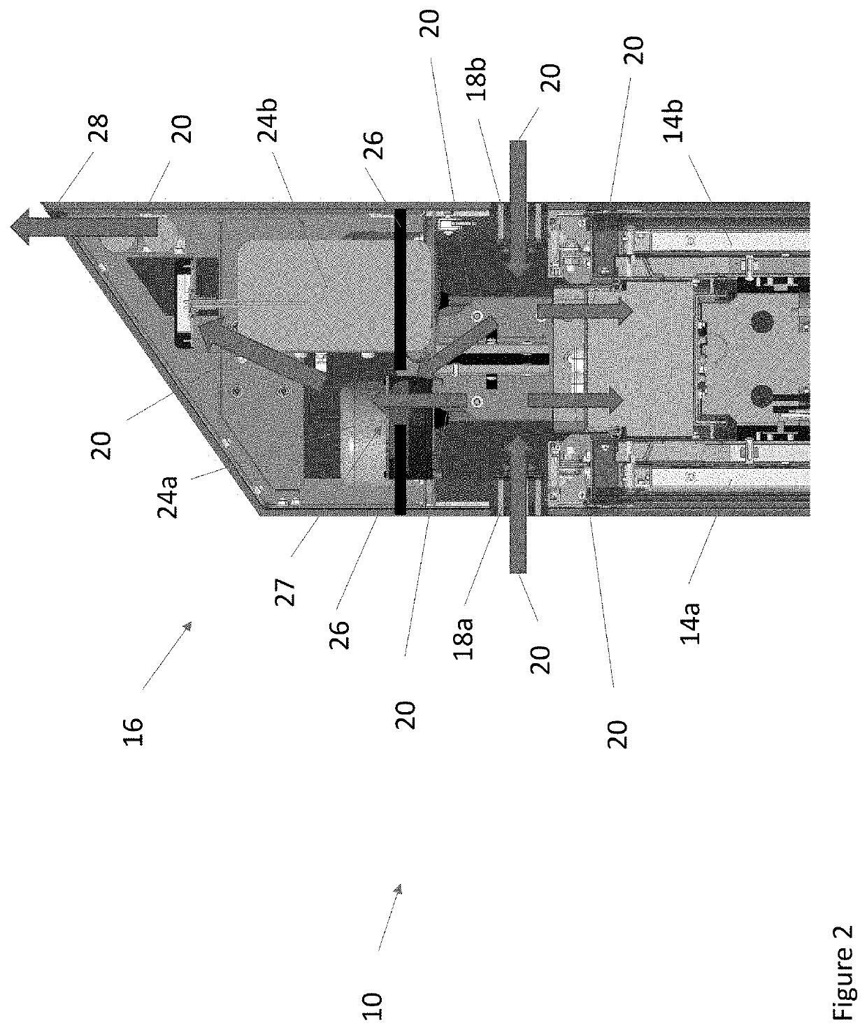
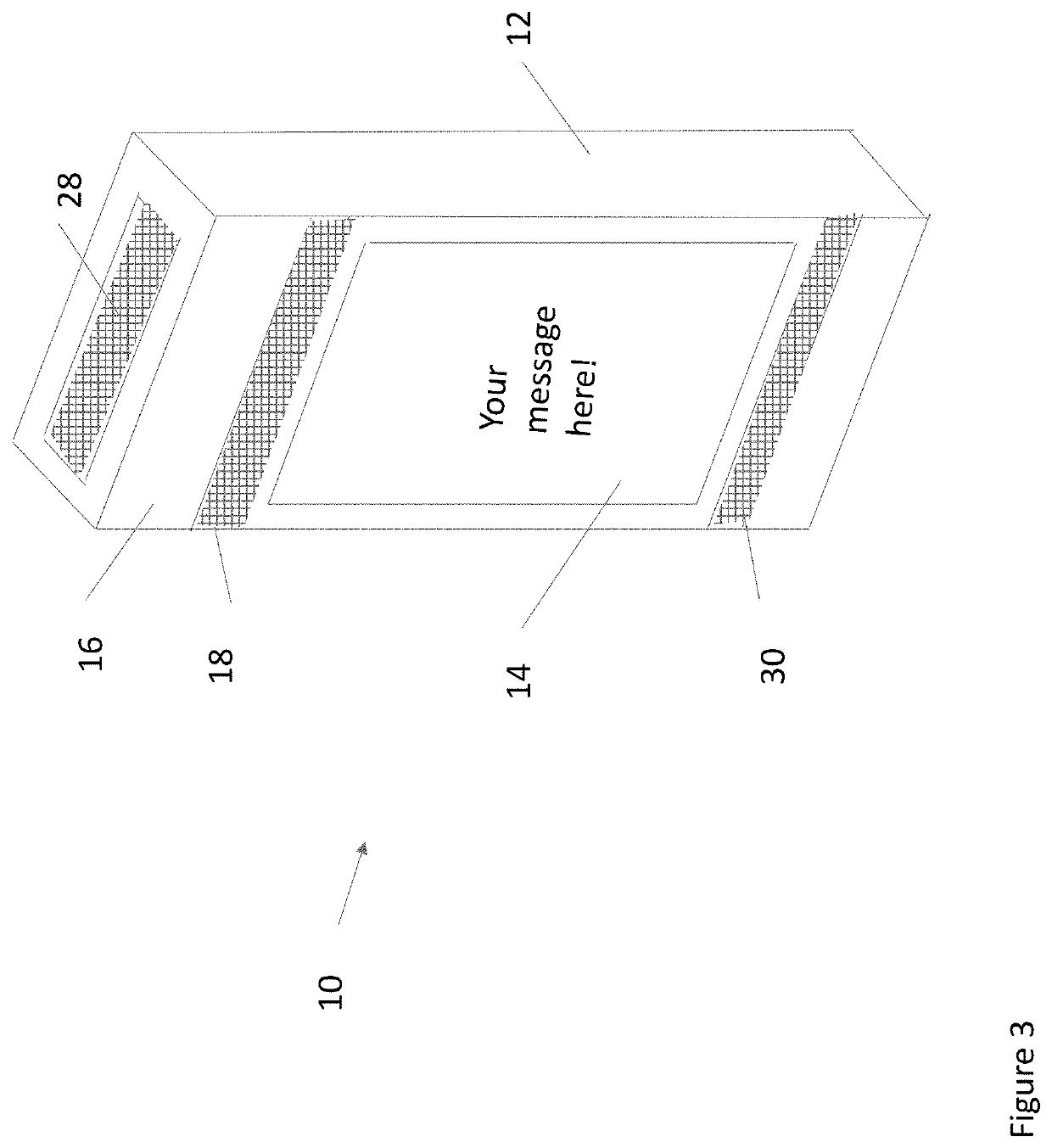
The patent text describes a field customizable airflow system for a communications box that includes a display assembly with electronic equipment. The system includes convection aperture plates with apertures that force air to pass by certain electronic components, creating areas of high or low airflow and cooling as required. The convection aperture plates can be retrofitted into existing display assemblies and replaced or added as needed to address the airflow needs of the electronic equipment. The air in the communications box may comprise ingested ambient air or circulating gas with thermal devices to remove heat. The technical effects of the patent include improved airflow and cooling for electronic equipment in ruggedized housing, flexibility in airflow needs over time, and efficient airflow system that can adjust to different equipment configurations.

Problems solved by technology

Lack of adequate airflow may result in equipment failure, improper operation, or undesirable consequences.

Method used


Image

  • Field customizable airflow system for a communications box
  • Field customizable airflow system for a communications box
  • Field customizable airflow system for a communications box

Examples


Embodiment Construction

)

[0027]Various embodiments of the present invention will now be described in detail with reference to the accompanying drawings. In the following description, specific details such as detailed configuration and components are merely provided to assist the overall understanding of these embodiments of the present invention. Therefore, it should be apparent to those skilled in the art that various changes and modifications of the embodiments described herein can be made without departing from the scope and spirit of the present invention. In addition, descriptions of well-known functions and constructions are omitted for clarity and conciseness.

[0028]Embodiments of the invention are described herein with reference to illustrations of idealized embodiments (and intermediate structures) of the invention. As such, variations from the shapes of the illustrations as a result, for example, of manufacturing techniques and / or tolerances, are to be expected. Thus, embodiments of the invention ...


PUM

PropertyMeasurementUnit
sizeaaaaaaaaaa
shapeaaaaaaaaaa
perimeteraaaaaaaaaa

Abstract

Field customizable airflow systems, and methods related to the same, are provided. A housing for an electronic display subassembly includes an intake and an exhaust for ambient air. A communications box located above the electronic display subassembly includes one or more electronic components, a convection aperture plate with one or more apertures, an intake portion, an exhaust portion, and one or more fans which cause a flow of ambient air to be accepted at the intake portion, circulated through each of the apertures in the convection aperture plate, and exhausted through the exhaust portion when activated.

Description

CROSS-REFERENCE TO RELATED APPLICATIONS[0001]This application makes no priority claim.TECHNICAL FIELD[0002]Exemplary embodiments relate generally to a field customizable airflow system for a communications box and systems and methods related to the same.BACKGROUND AND SUMMARY OF THE INVENTION[0003]It has become increasingly desirable to include certain electronic equipment with display assemblies featuring electronic displays. Such electronic equipment may include, for example, communications equipment, sensing equipment, combinations thereof, and the like. For example, advertising or announcements may be displayed at the electronic displays and internet connectivity may be facilitated by the electronic equipment. Such electronic displays and electronic equipment may be provided in ruggedized housings to protect the electronic displays and equipment from harsh environmental conditions. Sometimes, the electronic equipment is provided in a box above the electronic displays. The elevat...

Claims


Application Information

Patent Timeline
Patent Type & Authority Applications(United States)
IPC IPC(8): H05K7/20G02F1/1333
CPCH05K7/20972H05K7/20145G02F1/133385G02F1/133382G02F2201/36
Inventor BROWN, MIKE
Owner MFG RESOURCES INT INC
Learn More