Electric snowblower

Pending Publication Date: 2022-03-31
BONNEY MICHAEL ALLEN
View PDF0 Cites 0 Cited by
  • Summary
  • Abstract
  • Description
  • Claims
  • Application Information

AI Technical Summary

Benefits of technology

The invention is a two-stage electric powered snowblower that has an auger and a blower. The snowblower has two electric motors, one for the auger and one for the blower, which are positioned close together and operatively connected to the drive shaft. The blower motor is attached to the drive shaft or a hub, allowing it to rotate with respect to the drive shaft. The snow blower also has a gearbox and drive wheels that are powered by the electric motors. The technical effect of the invention is a snowblower that is efficient and effective in snow removal, with improved performance and control.

Problems solved by technology

As can be appreciated, this can lead to problems of clogging depending upon the size of the opening and the snow and ice conditions.
This creates the need for complicated gearboxes to provide a high-speed drive to the blower and a lower speed drive to the auger.
Additionally, if the auger is slowed down, stopped, or clogged due to heavy snow or ice, the blower is also slowed down or stopped since they are commonly driven by the same drive shaft.
This makes the clearing of the snowblower more difficult.
But the '144 suffers from the same problems as gas powered snow blowers, a single engine driving the auger and the blower.

Method used


Image

  • Electric snowblower
  • Electric snowblower
  • Electric snowblower

Examples


Embodiment Construction

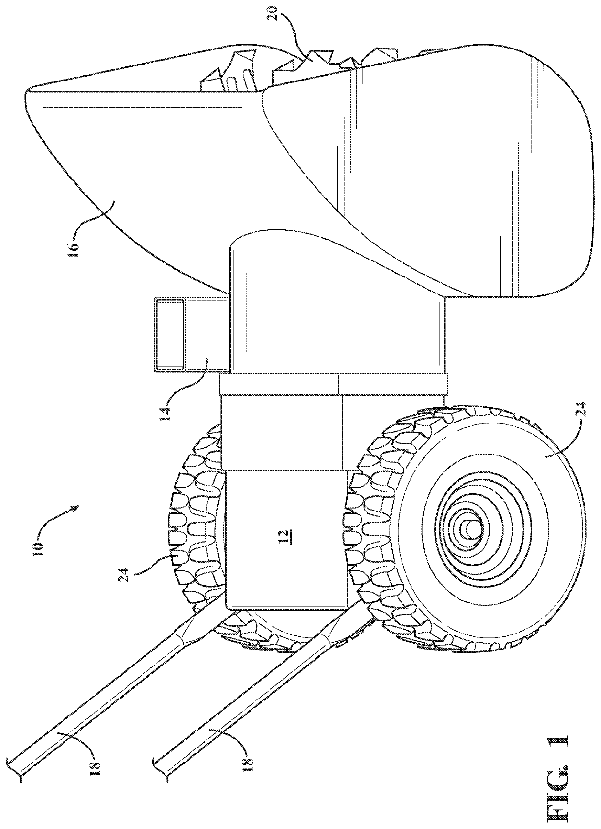
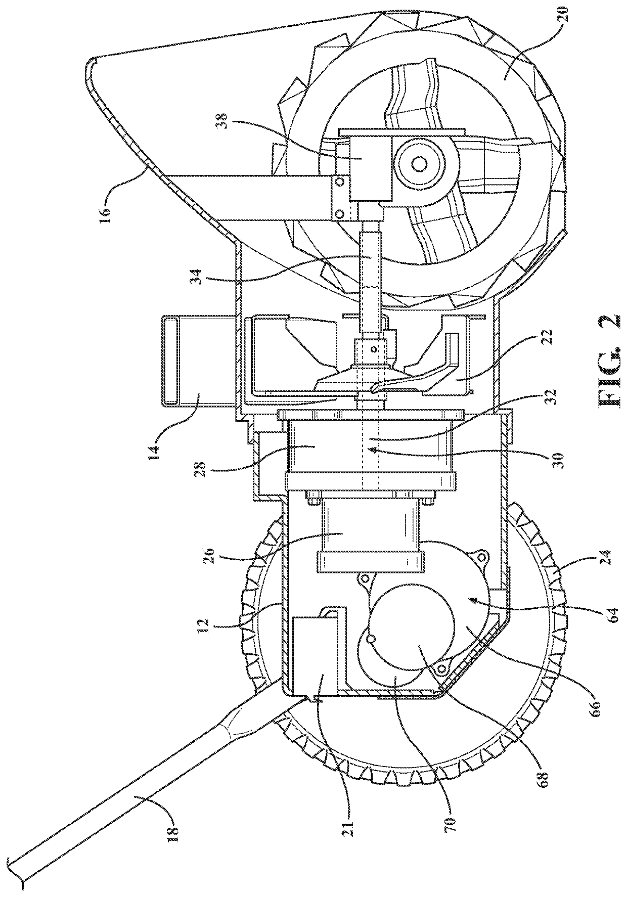
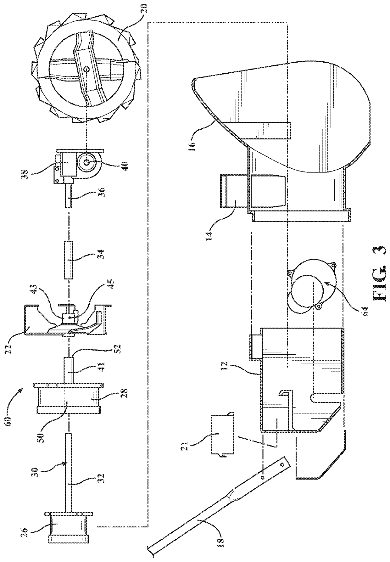
[0019]The snowblower of the present invention is shown generally at 10 in FIGS. 1 through 3 and 5. The illustrated snowblower 10 has a motor housing 12, a snow chute 14 and an auger housing 16. Control handles 18 are partially shown. The handles 18 extend to a control panel not shown.

[0020]The control panel includes the controls for operating the snowblower 10. Controls are provided for controlling the auger 20 and its speed, the blower 22 and its speed and the drive wheels 24 and their speed. The controls can also independently control the direction, either forward or reverse of the auger 20, and drive wheels 24. Controlling the direction of the wheels 24 allows the user to drive the snowblower 10 in forward and reverse. In addition to controlling the wheels 24 in the forward and reverse directions, there is an option to independently control each wheel 24 to aid in steering the snowblower 10. Controlling the direction of the auger 20 allows the operator to easily clean any snow or...


PUM


Abstract

Disclosed is a two-stage electric powered snowblower. It has an auger, a blower, and a main drive shaft. A first electric motor is operably coupled to the drive shaft to rotate the drive shaft at a desired speed. The drive shaft is operably coupled to the auger to rotate the auger. The auger rotates to pull snow into the snowblower housing so that it can be forced out of a chute in the desired direction. A second electric motor is operably coupled to the blower to drive the blower at a desired speed which is typically higher than the speed of the auger. The second electric motor is mounted adjacent the first electric motor. The blower is operably coupled to the second electric motor. The drive shaft extends through the second electric motor the blower.

Description

RELATED APPLICATIONS[0001]This application claims the benefit of U.S. Provisional Application No. 63 / 085,869 filed on Sep. 30, 2020.STATEMENT REGARDING FEDERALLY SPONSORED RESEARCH[0002]NONE.TECHNICAL FIELD[0003]This invention relates generally to snowblowers and more particularly to two stage snowblowers.BACKGROUND OF THE INVENTION[0004]Gas powered snow blowers are very common. They typically are either single stage or dual stage. Single stage gas snow blowers have an auger directly coupled to the gas motor. The auger rotates to force snow up through a discharge chute. Dual stage gas snow blowers have a blower adjacent to the discharge chute and an auger. The auger pulls snow into the snow blower and adjacent the chute. The blower then forces the snow out of the chute. With both the single and dual stage snow blowers, you manually adjust the chute to determine the direction and extent of snow thrown from the chute. Typically, this the user rotates the shoot in the direction where s...

Claims


Application Information

Patent Timeline
IPC IPC(8): E01H5/09E01H5/04
CPCE01H5/098E01H5/045
Inventor BONNEY, MICHAEL ALLEN
Owner BONNEY MICHAEL ALLEN
Why Eureka
Try Eureka