Waveform Energy Generation Systems and Methods of Enhandling Matrix Permeability in a Subsurface Formation
a waveform energy and subsurface technology, applied in the field of hydrocarbon recovery operations, can solve the problems of opening up natural occurring cemented and uncemented fractures, cementitious minerals to fail, etc., and achieve the effect of increasing the effective permeability of the rock matrix
- Summary
- Abstract
- Description
- Claims
- Application Information
AI Technical Summary
Benefits of technology
Problems solved by technology
Method used
Image
Examples
second embodiment
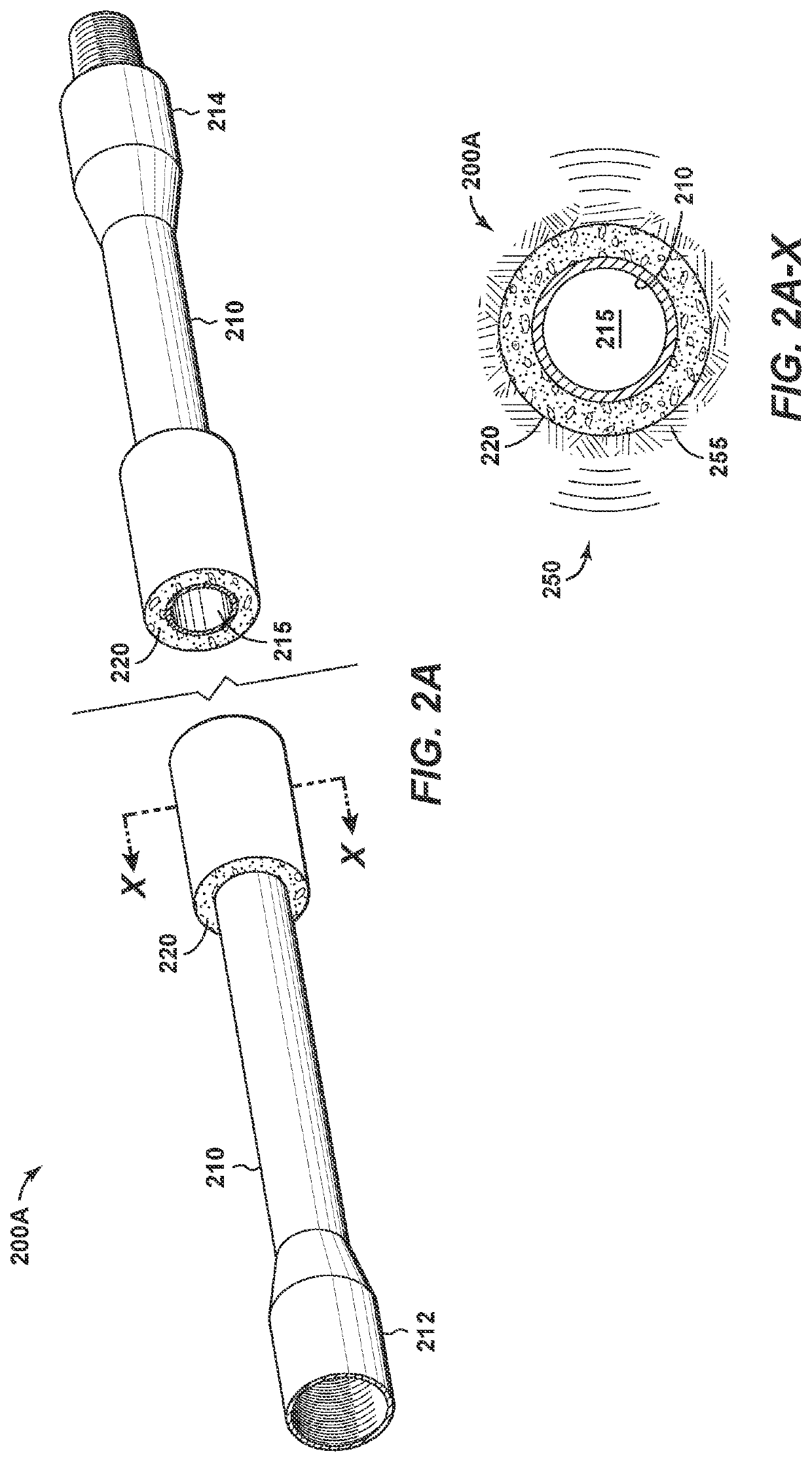
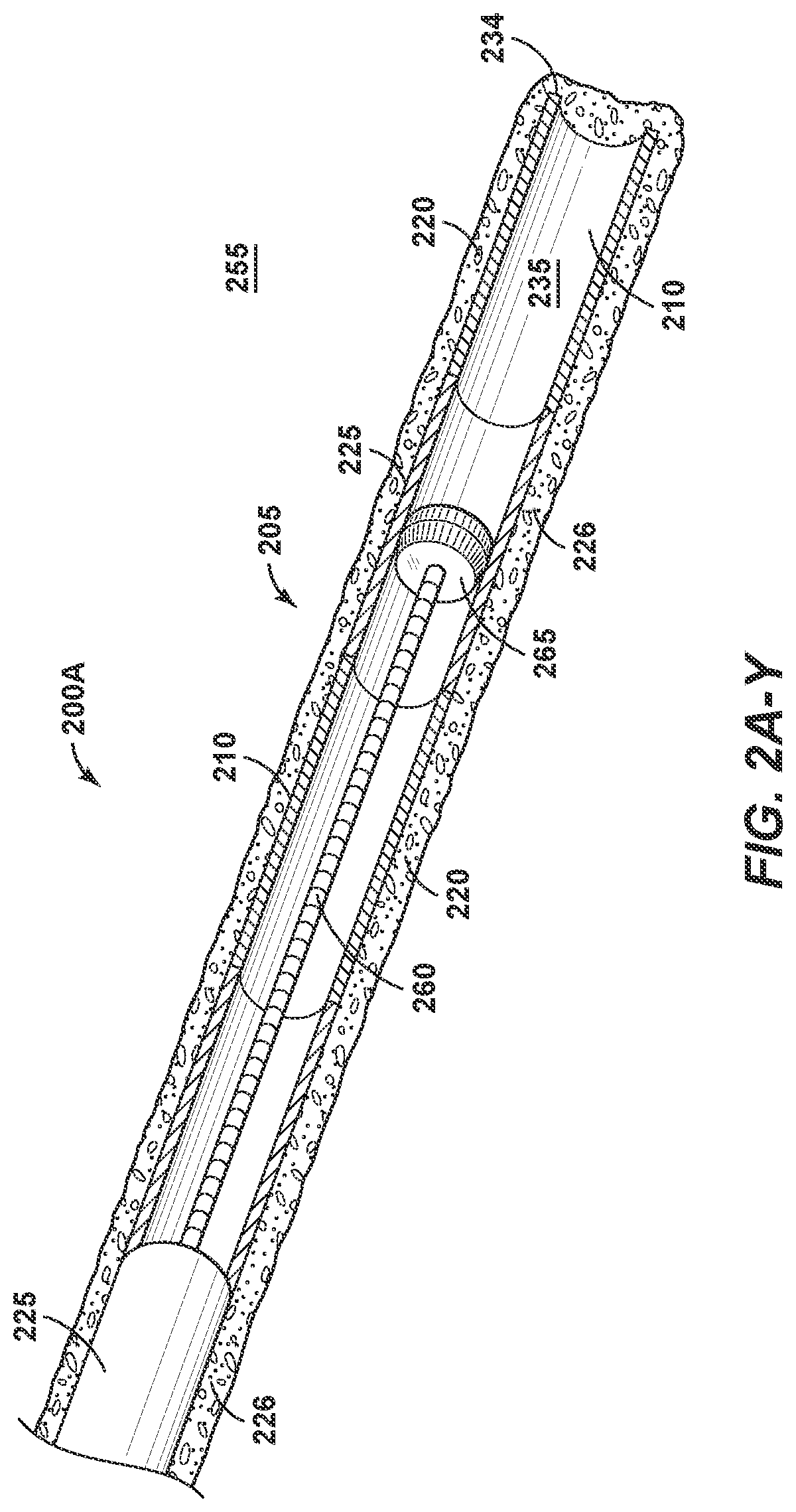
[0097]In the arrangements of FIGS. 2A and 2A-Y, the cement column 220 serves as the medium for generating waveform energy into the surrounding rock matrix in the subsurface formation 255. However, other systems and methods are offered herein for delivering wave energy into a formation through the excitation of piezo-electric materials. FIG. 2B is a perspective view of a joint of production casing 200B in a The joint of production casing 200B again includes a tubular body 210 having opposing first end 212 and second end 214. In this view, piezo-electric material is provided along discrete portions 216 of the production casing 200B.
[0098]The discrete portions 216 may represent areas along the tubular body 210 of the production casing 200B where piezo-electric material is located, such as by a coating. Alternatively, the discrete portions 216 may represent pads that are rotationally fixed along the outer diameter of the tubular body 210, such as by an adhesive connection or a friction...
third embodiment
[0101]FIG. 2C is a perspective view of a joint of production casing 200C in a In this view, acoustic devices 230 are secured to the production casing 200C. Each of the acoustic devices 230 comprises an elongated housing, or node, residing along an outer diameter of the production casing 200C. The acoustic devices 230 are dimensioned to contact the surrounding borehole when the production casing 200C is cemented into place within the wellbore.
[0102]Within each of the housings of the acoustic devices 230 is an acoustic energy generator. The acoustic energy generator of the acoustic device 230 may be, for example, an air gun. Upon detonation, each acoustic energy generator of the acoustic device 230 may apply between about 100 kHz and 1,000 kHz over a duration needed to grow the cumulative mechanical energy in the matrix that reaches the rock matrix failure point. The pressure amplitude and time for each pulse is controlled from the surface 105.
[0103]A series of joints forming the pro...
fourth embodiment
[0108]FIG. 2D is a perspective view of a joint of production casing 200D in a In this view, explosive devices 240 are secured to the production casing 200D. Each of the explosive devices 240 comprises an elongated housing residing along an outer diameter of the production casing 200D. The explosive devices 240 are dimensioned to contact or to reside closely adjacent to the surrounding borehole or subsurface formation when the production casing 200D is cemented into place within the wellbore.
[0109]Within each of the housings of the explosive devices 240 are charges. The charges represent explosive charges generated by using a length of primer cord and / or a blast cap. Of course, the charges are not accompanied by any actual shots (this is not a perforating gun). Preferably, multiple explosive devices 240 are spaced around the casing body 210, and multiple production casings 200D are connected end-to-end along the wellbore. The explosive devices 240 are then fired together or in seque...
PUM
 Abstract
Description
Claims
Application Information
 - R&D
- Intellectual Property
- Life Sciences
- Materials
- Tech Scout
- Unparalleled Data Quality
- Higher Quality Content
- 60% Fewer Hallucinations
Browse by: Latest US Patents, China's latest patents, Technical Efficacy Thesaurus, Application Domain, Technology Topic, Popular Technical Reports.
© 2025 PatSnap. All rights reserved.Legal|Privacy policy|Modern Slavery Act Transparency Statement|Sitemap|About US| Contact US: help@patsnap.com


