Formed plunger apparatus

a plunger and plunger technology, applied in the field of plungers, can solve the problems of inability to use bolts, impractical or impossible access to threaded ends, and difficulty in manufacturing safety bolts, and achieve the effect of optimizing costs associated

Pending Publication Date: 2022-02-24
PIVOT POINT
View PDF11 Cites 0 Cited by
  • Summary
  • Abstract
  • Description
  • Claims
  • Application Information

AI Technical Summary

Benefits of technology

The present invention provides an improved formed plunger apparatus with a wedge or other shape that is easy to install. The plunger is constructed in a single piece with a base, which simplifies the manufacturing process and reduces costs. The absence of a biasing section in the plunger eliminates the need for an expensive and complicated part. Overall, this invention provides a more efficient and cost-effective plunger apparatus for use in self-locking pins.

Problems solved by technology

However, these dual fasteners make safety bolts more difficult and thus more expensive to manufacture.
Additionally there are some applications where such a bolt cannot be used because it is either impractical or impossible to access the threaded end of the bolt after it is inserted through an aperture.
Also, screwing the nut on the end of the bolt causes an increase in assembly time.
However, dimensional restrictions, and cost optimization, may necessitate a plunger reducing, if not removing, the spring or biasing section.

Method used


Image

  • Formed plunger apparatus
  • Formed plunger apparatus
  • Formed plunger apparatus

Examples


Embodiment Construction

[0040]Although the disclosure hereof is detailed and exact to enable those skilled in the art to practice the invention, the physical embodiments herein disclosed merely exemplify the invention which may be embodied in other specific structures. While the preferred embodiment has been described, the details may be changed without departing from the invention, which is defined by the claims.

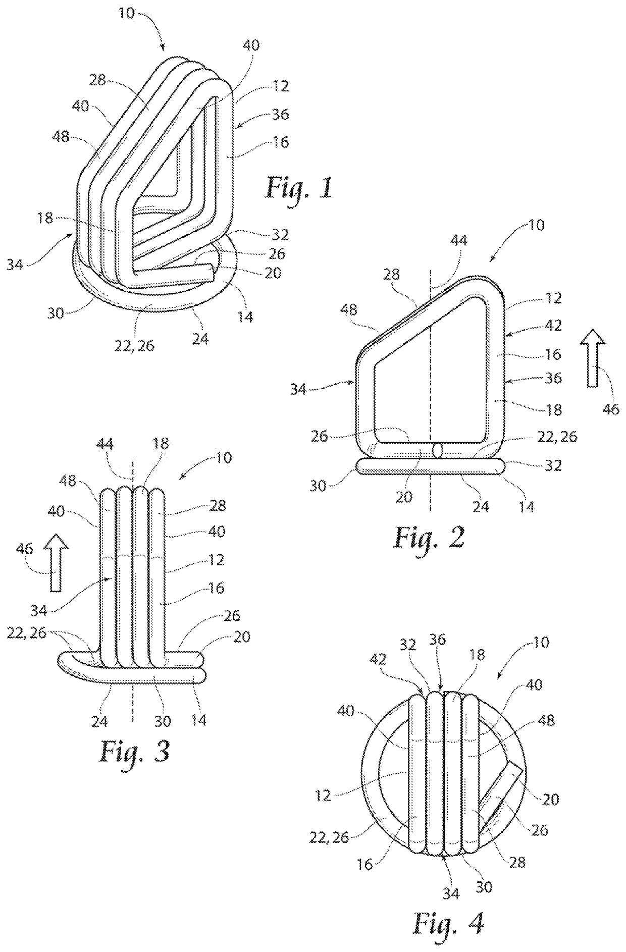
[0041]With attention to FIGS. 1 to 4, a first embodiment of a plunger of the invention 10 is illustrated. The plunger 10 comprises a plunger section 12 and a base section 14 in unitary one-piece construction. As illustrated, the first embodiment of the plunger 10 provides for the plunger 10 as a wire 16 wound in a substantially circular manner to provide for the base section 14. The base section 14 comprises a base section first side 22 and a base section second side 24, opposite the first side 22. The base section 14 is at least substantially planar in configuration, wherein the first side 22 and...


PUM


Abstract

An improved plunger for a self-locking pin having a plunger section and a base section in a unitary one-piece construction, wherein the plunger section is at least substantially orthogonal to the base section. Wherein the base section comprises at least a substantially planar configuration, and may provide for biasing of the plunger section. A portion of the plunger extends outwardly from a bore of the self locking pin in which the plunger resides. The plunger section is preferably wedge-shaped, or may possess other geometrical shapes, while the portion of the plunger disposed inside the bore is of a cylindrical shape. An extended biasing section tor positioning of the plunger section may be in unitary construction with the base section.

Description

BACKGROUND OF THE INVENTION[0001]The invention relates to fasteners, namely threadless fasteners for retaining two or more structures through apertures formed in each structure. More specifically, the invention relates to plunger assemblies of the threadless fasteners.[0002]Detent pins are well known in industry. Many of these pins fall into the category of safety bolts. Safety bolts have a threaded end to which a nut can be attached to as well as a detent mechanism along the length of the bolt. The main fastening mechanism in safety bolts is threading the nut on the end of the bolt. These products are often used in the aircraft industry so an extra safety factor is present in case vibrations cause the nut to loosen or someone forgets to tighten the nut. The detent mechanism is this extra safety factor. However, these dual fasteners make safety bolts more difficult and thus more expensive to manufacture. Additionally there are some applications where such a bolt cannot be used becau...

Claims


Application Information

Patent Timeline
Patent Type & Authority Applications(United States)
IPC IPC(8): F16B21/12
CPCF16B21/125F16B2021/14F16B2/248F16B21/14Y10T403/604
Inventor BAUS, ROMAN J.LEITZKE, SOL
Owner PIVOT POINT
Why Eureka
Try Eureka