
Display panel and display device

a display device and display panel technology, applied in the field of displays, can solve the problems of low lifespan, limited basic functions, easy damage, etc., and achieve the effects of improving the overall attractive appearance of the display device, reducing the influence of the camera position, and improving the screen-to-body ratio

Active Publication Date: 2022-02-17
WUHAN CHINA STAR OPTOELECTRONICS TECH CO LTD
View PDF0 Cites 0 Cited by
  • Summary
  • Abstract
  • Description
  • Claims
  • Application Information

AI Technical Summary

Benefits of technology

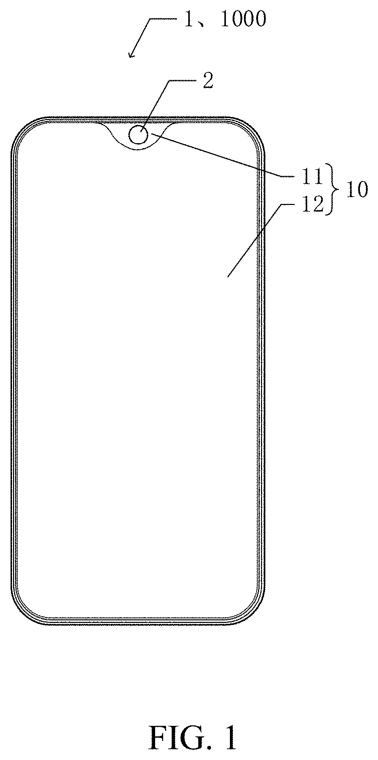
This patent is about a new display panel and device that combines two different liquid crystal display technologies. The panel has a transparent area and an opaque area. When the camera is turned on, the transparent area is in a transparent state to create a light channel for the camera. When the camera is turned off, the transparent area can display an image normally, improving the screen-to-body ratio and creating a full-screen display. This improves the overall attractive appearance of the display device and enhances the user's experience.

Problems solved by technology

However, it is limited by basic functions that are indispensable for mobile phones such as a front camera, an earpiece, a distance sensor, and a light sensor, so that at present, there is a notch in an upper part of the screen of the mobile display device to dispose the above functional components.
However, the display device with the lifting camera has disadvantages of being non-waterproof, having a low lifespan, being easily damaged, and low quality user experience.

Method used


Image

  • Display panel and display device
  • Display panel and display device
  • Display panel and display device

Examples


Embodiment Construction

[0036]Preferred embodiments of the present disclosure will be introduced with reference to appended drawings as follows to demonstrate that the present disclosure may be implemented. The embodiment of the present disclosure can be fully introduced to those skilled in the art to make technical contents more clear and easy to understand. The present disclosure can be embodied in many different forms of embodiment, and the scope of protection of the present disclosure is not limited to the embodiments set forth herein.

[0037]In the accompanying drawings, structurally identical components are designated by the same reference numerals, and structurally or functionally similar components throughout are designated by similar numerical reference numerals. The dimensions and thicknesses of each component shown in the drawings are arbitrarily shown. The size and thickness of each component are not limited, and for the sake of clarity, the thickness of the components is exaggerated somewhat in ...


PUM

PropertyMeasurementUnit
transparentaaaaaaaaaa
areaaaaaaaaaaa
attractiveaaaaaaaaaa

Abstract

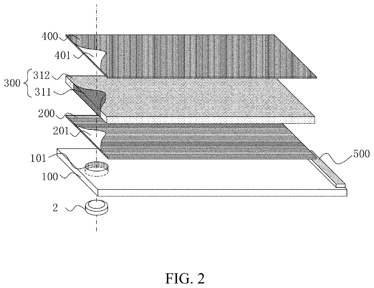
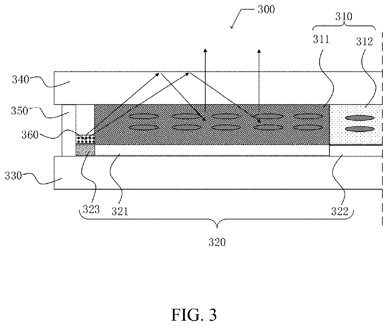
A display panel and a display device are provided. The display panel includes a display area including a transparent display area and an opaque display area surrounding the transparent display area. In the display area, the display panel also includes a backlight and a liquid crystal display panel. The backlight includes a first through hole corresponding to the transparent display area. The liquid crystal display panel is disposed over the backlight. The liquid crystal display panel includes a driving layer and a liquid crystal layer. The driving layer includes a first driving circuit and a second driving circuit. The liquid crystal layer includes a first liquid crystal region corresponding to the transparent display area and a second liquid crystal region corresponding to the opaque display area. The first driving circuit corresponds to the first liquid crystal region. The second driving circuit corresponds to the second liquid crystal region.

Description

FIELD OF DISCLOSURE[0001]The present disclosure relates to the field of displays, and in particular to a display panel and a display device.BACKGROUND[0002]Smart terminals such as mobile phones and tablet computers are becoming an indispensable part of people's daily life due to their convenience, entertainment, and functional diversity. With the continuous development of display technology, applications of more advanced technologies on smart terminals have greatly enriched people's lives. At the same time, people's requirements and expectations for smart terminals are getting higher and higher. While enjoying basic functions brought by smart terminals such as mobile phones and tablet computers, people also put forward higher requirements for smart terminals, such as a full-screen design of smart terminals.[0003]Full-screen technology is a broader definition of a mobile phone design for ultra-high screen-to-body ratio in a display industry. Literally, a front of the phone is occupie...

Claims


Application Information

Patent Timeline
Patent Type & Authority Applications(United States)
IPC IPC(8): G02F1/13357G02F1/1335G02F1/1339
CPCG02F1/133603G02F1/1339G02F1/133531G02F1/133504G02F1/137G02F1/1333G02F1/133388G02F1/133G02F1/133331G02F1/133605G02F1/133608
Inventor SUN, YUANWANG, CHAOLIU, GUANGHUI
Owner WUHAN CHINA STAR OPTOELECTRONICS TECH CO LTD
Learn More