
Display panel and display device

a display panel and display panel technology, applied in the field of display, can solve the problems of reducing the screen-to-body ratio of the display panel of the handheld device, breaking the integrity of the display region, etc., and achieve the effect of improving the user experience and increasing the screen-to-body ratio

Inactive Publication Date: 2020-09-10
WUHAN CHINA STAR OPTOELECTRONICS SEMICON DISPLAY TECH CO LTD
View PDF0 Cites 0 Cited by
  • Summary
  • Abstract
  • Description
  • Claims
  • Application Information

AI Technical Summary

Benefits of technology

The present invention provides a display panel and a display device that do not need to be set in a special shape to bypass functional devices. This improves the screen-to-body ratio and enhances the user experience. The technical effect of this invention is to provide a more efficient and effective display design that optimizes screen usage and provides a better user experience.

Problems solved by technology

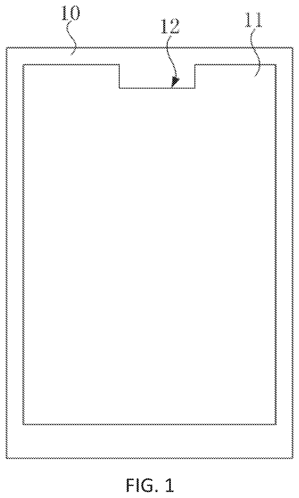
A disadvantage of the above structure is that a display region needs to be set to a special shape to bypass a location on which the functional devices are disposed, which breaks the integrity of the display region and reduces the screen-to-body ratio of a display panel of a handheld device.

Method used


Image

  • Display panel and display device
  • Display panel and display device
  • Display panel and display device

Examples


Embodiment Construction

[0029]The specific embodiments of the display panel and the display device provided by the present invention will be described in detail below with reference to the accompanying drawings.

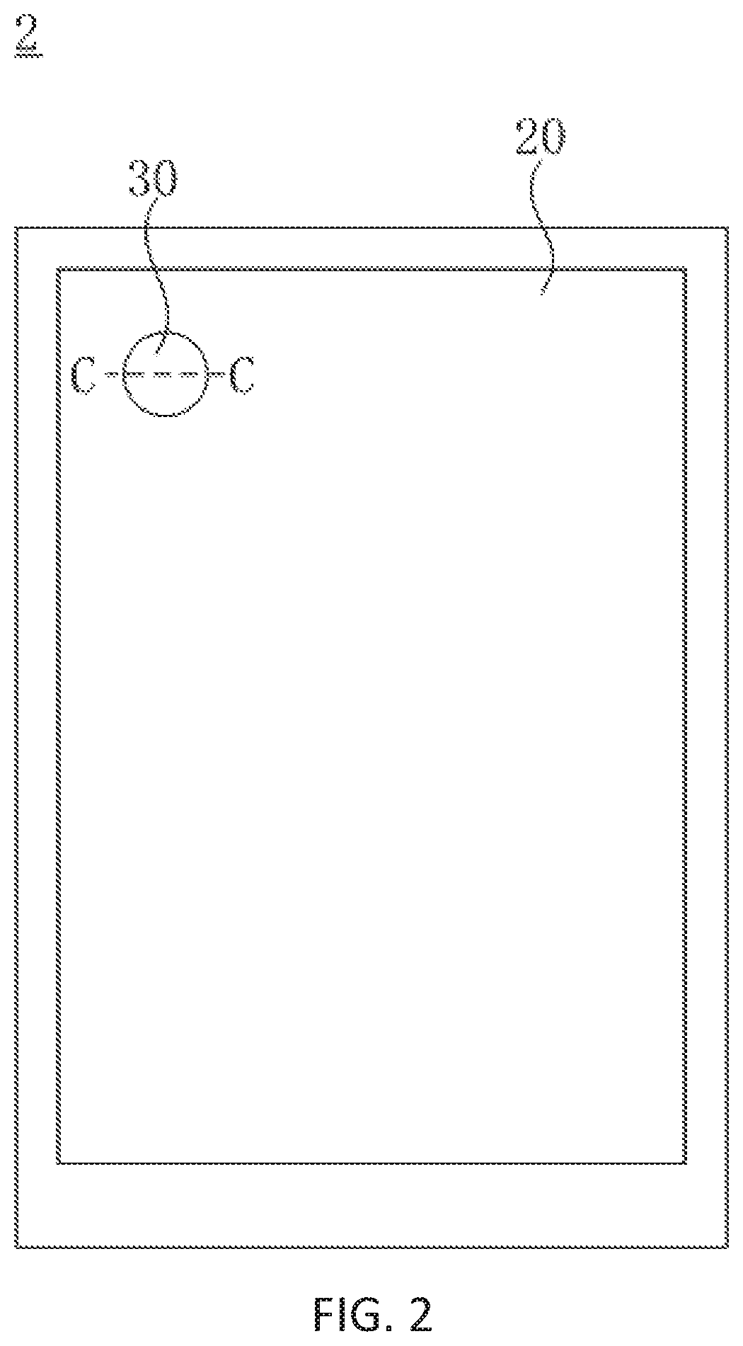
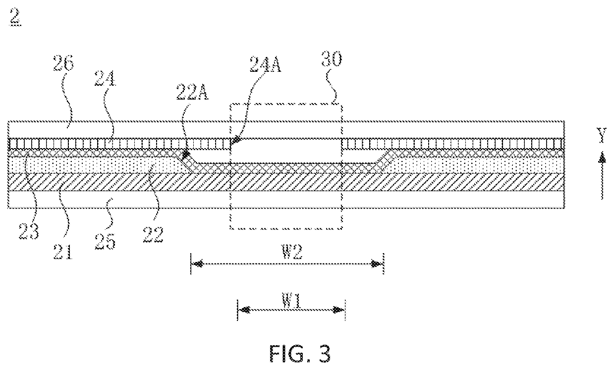
[0030]FIG. 2 is a top plan view of the first embodiment according to the display panel of the present invention. FIG. 3 is a sectional view of a C-C line in FIG. 2. As shown in FIG. 2 and FIG. 3, a display panel 2 includes a display region 20 and a light transmission region 30. The display region 20 is configured to display an image. The light transmission region 30 is configured to transmit visible light therethrough, that is, visible light can be transmitted from a light-emitting surface of the display panel 2 to a non-light-emitting surface of the display panel 2 in the light transmission region 30. The display region 20 covers the light transmission region 30, that is, an edge of the transmission layer 30 is isolated from an edge of the display region 20.

[0031]The display panel 2 includes a plur...


PUM


Abstract

A display panel and a display device are provided. The display panel do not need to be set to a special shape to provide a region where a functional device disposed on, which is beneficial to increase the screen-to-body ratio and improve the user experience.

Description

FIELD OF INVENTION[0001]The present invention relates to a field of display, and, more particularly, to a display panel and a display device.BACKGROUND OF INVENTION[0002]To increase the screen-to-body ratio of an electric product, a non-display region on a display panel is compressed smaller and smaller. For instance, in a display panel of a mobile phone or a handheld terminal, functional devices of the handheld terminal, such as a front camera and an earphone, are disposed in a predetermined notch defined in a top side of a display region in order to compress the non-display region as much as possible.[0003]FIG. 1 is a top plan view of a conventional display panel. As shown in FIG. 1, a frame 10 with a flat panel shape covers a display region 11, wherein the frame 10 is a non-display region. A notch 12 is defined in a top portion of the display region 11. Functional devices like a front camera (not shown) and an earphone (not shown) are disposed in the notch 12 in order to prevent ...

Claims


Application Information

Patent Timeline
Patent Type & Authority Applications(United States)
IPC IPC(8): H01L51/52
CPCH01L51/5253H01L51/5293H10K59/65H10K59/121H10K59/873H10K59/8791H10K50/844H10K50/868
Inventor ZHOU, SISI
Owner WUHAN CHINA STAR OPTOELECTRONICS SEMICON DISPLAY TECH CO LTD
Learn More