
Fastening device for holding a sensor, comprising a cam

a technology of fastening device and sensor, applied in the field of sensors, to achieve the effect of actuating quickly and easily

Active Publication Date: 2022-02-10
PAYRAUD PIERRE
View PDF0 Cites 0 Cited by
  • Summary
  • Abstract
  • Description
  • Claims
  • Application Information

AI Technical Summary

Benefits of technology

The present invention provides a fastening device with easily actuated axial-immobilization means, even in limited space. This device allows for the quick and reliable immobilization of sensors, providing a simple yet effective solution.

Problems solved by technology

This is a disadvantage when the fastening device is installed somewhere that is not readily accessible, or else in a confined space, as is often the case in machine tools or on an automated manufacturing line.

Method used


Image

  • Fastening device for holding a sensor, comprising a cam
  • Fastening device for holding a sensor, comprising a cam
  • Fastening device for holding a sensor, comprising a cam

Examples


Embodiment Construction

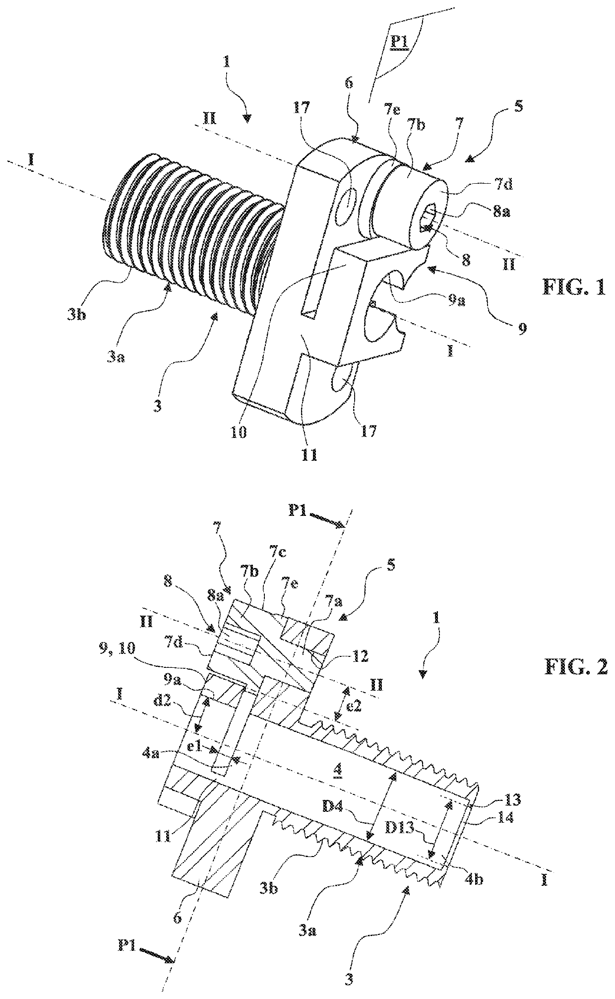
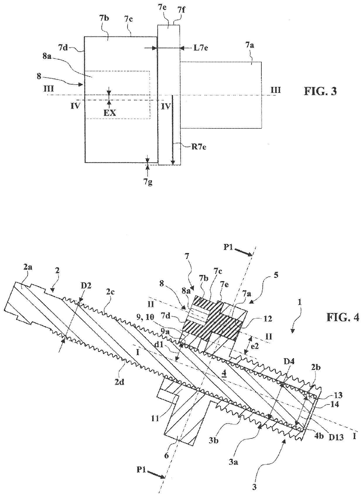
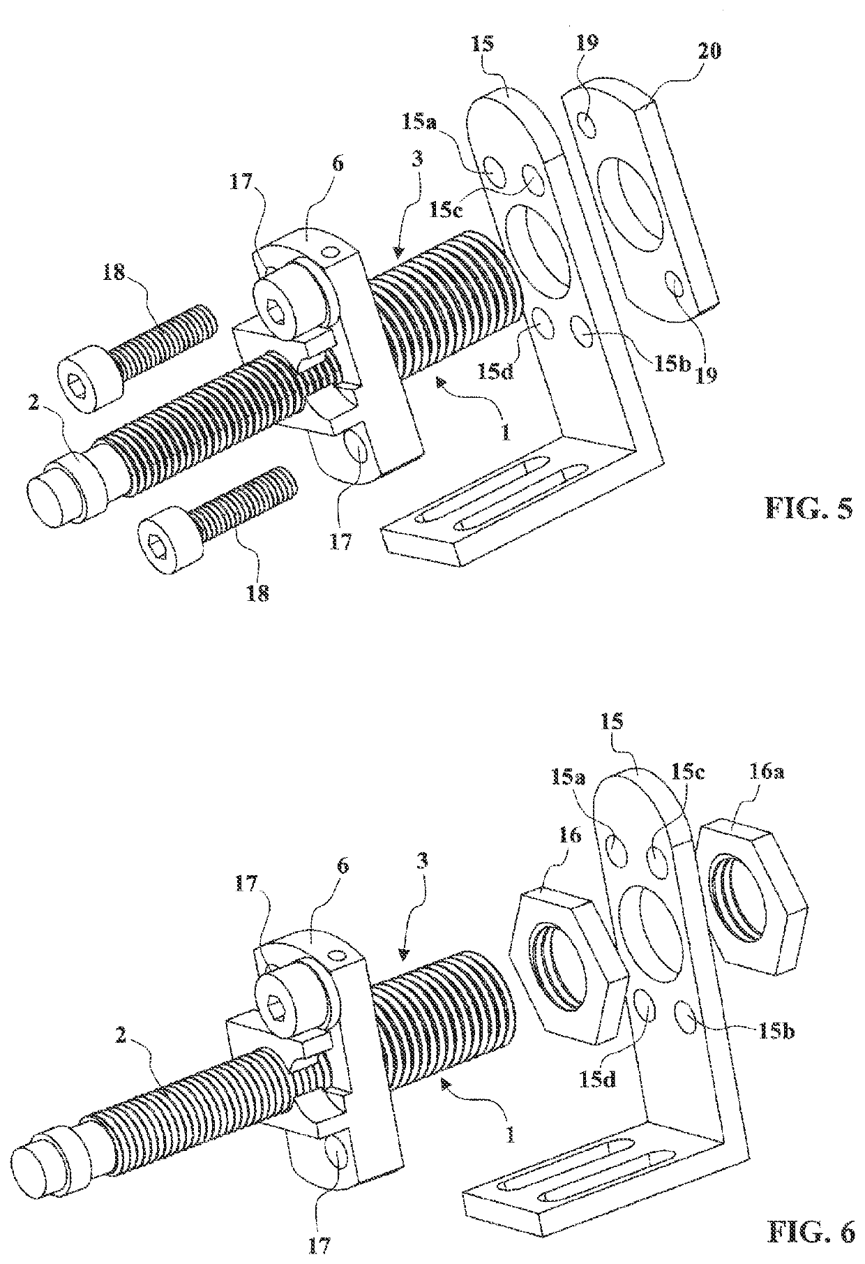
[0066]FIGS. 1 to 8 and 13 on the one hand, and FIGS. 9 to 12 on the other, respectively illustrate a first embodiment and a second embodiment of a fastening device 1 according to the present invention, which is intended to hold a sensor 2 of cylindrical shape bounded by a proximal end 2a and a distal end 2b (FIG. 4).

[0067]In all the embodiments, the fastening device 1 comprises:[0068]a body 3 comprising a longitudinal through-passage 4 extending along a first longitudinal axis I-I between a first end 4a and a second end 4b, said longitudinal through-passage 4 being intended to accept said sensor 2,[0069]axial-immobilization means 5 for immobilizing the sensor 2 in the longitudinal through-passage 4.

[0070]In more detail, the axial-immobilization means 5 comprise:[0071]a flange 6, solid with the body 3, flaring out radially from and away from the body 3 and the first longitudinal axis I-I,[0072]a cam 7 mounted with the ability to rotate on the flange 6 about a second longitudinal axis...


PUM


Abstract

A fastening device for holding a sensor includes a clamping piece which is acted on by a cam, in order to be movable between a release position and a clamping position.

Description

TECHNICAL FIELD OF THE INVENTION[0001]The present invention relates to the field of sensors and is more particularly concerned with a fastening device for holding a sensor.[0002]Proximity sensors having a cylindrical shape bounded by a proximal end and a distal end are known. These sensors may be capacitive, inductive, optoelectronic or of the fiber optic type for example, and usually have a circular cross section. Such sensors are used for example in machine tools or on automated manufacturing lines to detect the presence of an object and / or to measure the distance at which the object is situated. These sensors are removable and interchangeable, and their position needs to be able to be adjusted and fixed.[0003]In order to hold one of these sensors in a position that is fixed and adjustable in relation to their environment, fastening devices, comprising:[0004]a body comprising a longitudinal through-passage extending along a first longitudinal axis between a first end and a second ...

Claims


Application Information

Patent Timeline
Patent Type & Authority Applications(United States)
IPC IPC(8): G01D11/30
CPCG01D11/30
Inventor PAYRAUD, PIERRE
Owner PAYRAUD PIERRE
Learn More