
Cerebral spinal fluid shunt plug

a cervical spinal fluid and shunt plug technology, applied in the field of cervical spinal fluid shunt plugs, can solve the problems of abnormal dilation of the ventricles within the brain, accumulation of potentially harmful pressure on the tissues of the brain, and defect in the skull

Pending Publication Date: 2022-02-03
LONGEVITI NEURO SOLUTIONS LLC
View PDF0 Cites 0 Cited by
  • Summary
  • Abstract
  • Description
  • Claims
  • Application Information

AI Technical Summary

Benefits of technology

The present invention is related to a cerebral spinal fluid shunt plug that includes a housing with a shunt valve recess and a window recess with an access hole. The shunt plug also includes a shunt valve and an intracranial monitoring device. The access holes allow for connection of a ventricular catheter and a peritoneal catheter with the shunt valve. The window allows for optical, sonolucent, and radiolucent imaging and treatment. The window is optically transparent and can be a lucent disk with markings or channels. The invention provides improved cerebral spinal fluid shunt plugs for the treatment of hydrocephalus.

Problems solved by technology

The excessive accumulation results in abnormal dilation of the ventricles within the brain.
This dilation may cause the accumulation of potentially harmful pressure on the tissues of the brain.
In addition to common complications, such as shunt malfunction, shunt failure, and shunt infection, the utilization of catheters passing through the burr hole with the shunt valve positioned between the skull and the scalp results in other problems.
For example, the shunt valve may resorb bone thereby creating a defect in the skull.
In addition, the shunt valve and / or ventricular catheter are susceptible to movement.
Still further, the ventricular catheter is susceptible to kinks as it passes through and around the burr hole.

Method used


Image

  • Cerebral spinal fluid shunt plug
  • Cerebral spinal fluid shunt plug
  • Cerebral spinal fluid shunt plug

Examples


Embodiment Construction

[0054]The detailed embodiments of the present invention are disclosed herein. It should be understood, however, that the disclosed embodiments are merely exemplary of the invention, which may be embodied in various forms. Therefore, the details disclosed herein are not to be interpreted as limiting, but merely as a basis for teaching one skilled in the art how to make and / or use the invention.

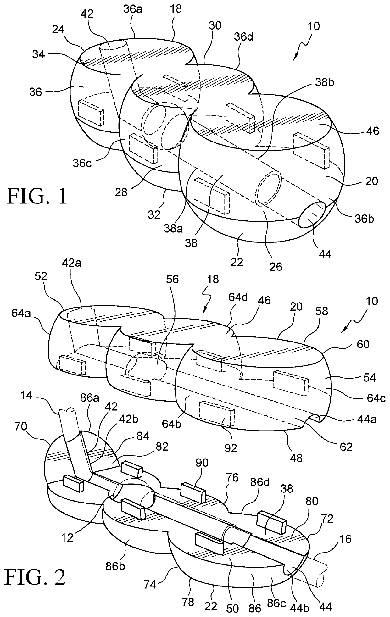
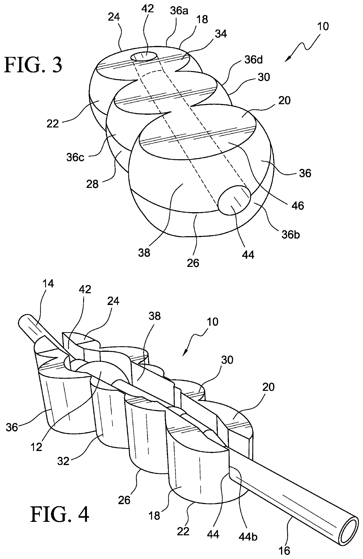
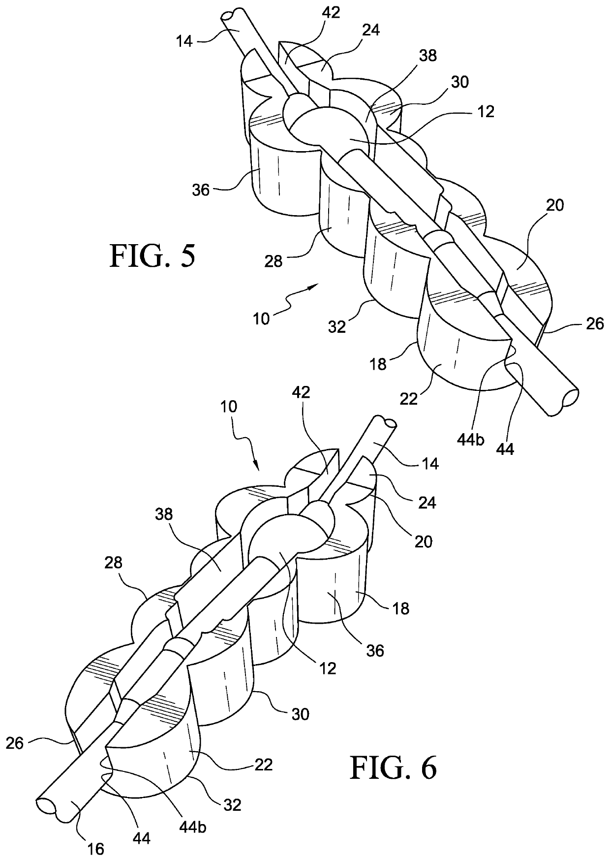
[0055]Referring to FIGS. 1 to 7, various embodiments of a cerebral spinal fluid shunt plug 10 are disclosed in accordance with the present invention. It should be appreciated similar reference numerals are used for the various different embodiments. The shunt plug 10 is shaped and dimensioned for positioning within a physician formed cranial hole 100. The shunt plug 10 is further shaped and dimensioned for housing a shunt valve 12 in a reliable and secure manner so that a ventricular catheter 14 and peritoneal catheter 16 may be positioned without fear that the shunt valve 12 might move and / or ...


PUM

PropertyMeasurementUnit
surface areaaaaaaaaaaa
optically transparentaaaaaaaaaa
optically translucentaaaaaaaaaa

Abstract

A cerebral spinal fluid shunt plug includes a shunt plug housing having a shunt valve recess formed therein and a window recess with an access hole. The cerebral spinal fluid shunt plug also includes a shunt valve shaped and dimensioned for positioning within the shunt valve recess of the shunt plug housing and a lucent disk shaped and dimensioned for the passage through the central access hole of the shunt plug housing. In another embodiment, a cerebral spinal fluid shunt plug includes a shunt plug housing having a shunt valve recess formed therein and an intracranial monitoring device recess with an access hole. A shunt valve is positioned within the shunt valve recess of the shunt plug housing and an intracranial monitoring device is passed through the central access hole of the shunt plug housing.

Description

CROSS REFERENCE TO RELATED APPLICATION[0001]This application claims the benefit of U.S. Provisional Application Ser. No. 63 / 092,606, entitled “CEREBRAL SPINAL FLUID SHUNT PLUG,” filed Oct. 16, 2020, and this application is a continuation in part of U.S. patent application Ser. No. 16 / 662,624, entitled “CEREBRAL SPINAL FLUID SHUNT PLUG,” filed Oct. 24, 2019, which is a continuation in part of U.S. patent application Ser. No. 15 / 830,529, entitled “CEREBRAL SPINAL FLUID SHUNT PLUG,” filed Dec. 4, 2017, which claims the benefit of U.S. Provisional Patent Application Ser. No. 62 / 488,966, entitled “CEREBRAL SPINAL FLUID SHUNT PLUG,” filed Apr. 24, 2017, which are incorporated herein by reference.BACKGROUND OF THE INVENTION1. Field of the Invention[0002]The present invention relates to a cerebral spinal fluid shunt plug.2. Description of the Related Art[0003]Hydrocephalus is a condition in which an excessive accumulation of cerebral spinal fluid is encountered. Cerebral spinal fluid is the...

Claims


Application Information

Patent Timeline
Patent Type & Authority Applications(United States)
IPC IPC(8): A61M27/00A61L29/06A61L29/14
CPCA61M27/006A61L29/06A61M2205/04A61M2205/3303A61M2205/3523A61L29/14A61B5/0004A61B5/031A61B5/6847A61L31/048A61L31/14C08L33/12
Inventor CHRISTOPHER, JESSERABINOVITZ, BRADLEYJOHNSON, TODD
Owner LONGEVITI NEURO SOLUTIONS LLC
Learn More