Interbody cage device and methods of use
a cage device and cage technology, applied in the field of implants used in spinal surgical procedures, can solve the problems of no method of selecting the size of the interbody fusion device which enables a controlled decompression, no method of approaching the spine of a patient for spinal interbody fusion or total disc replacement,
- Summary
- Abstract
- Description
- Claims
- Application Information
AI Technical Summary
Benefits of technology
Problems solved by technology
Method used
Image
Examples
first embodiment
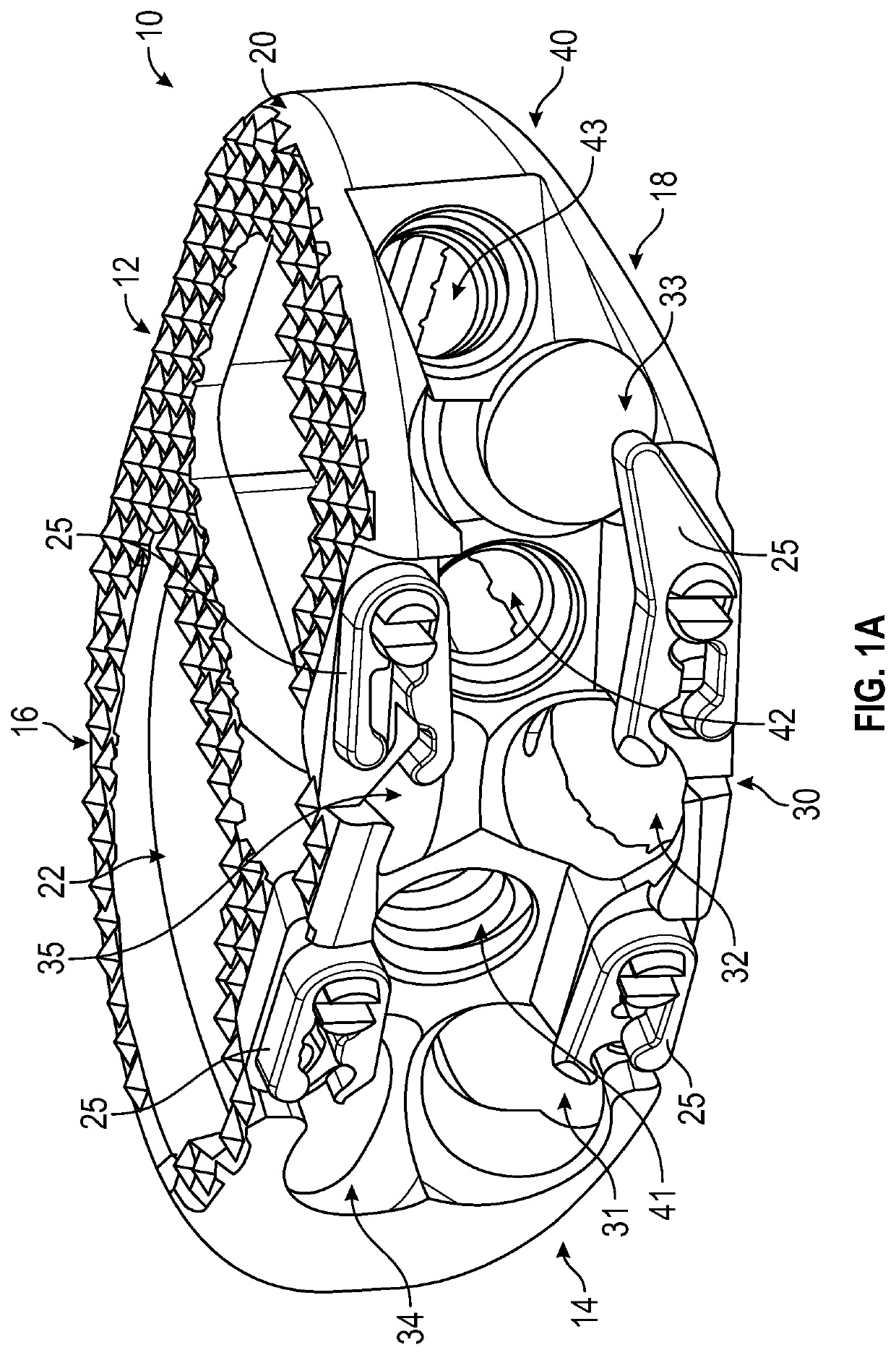
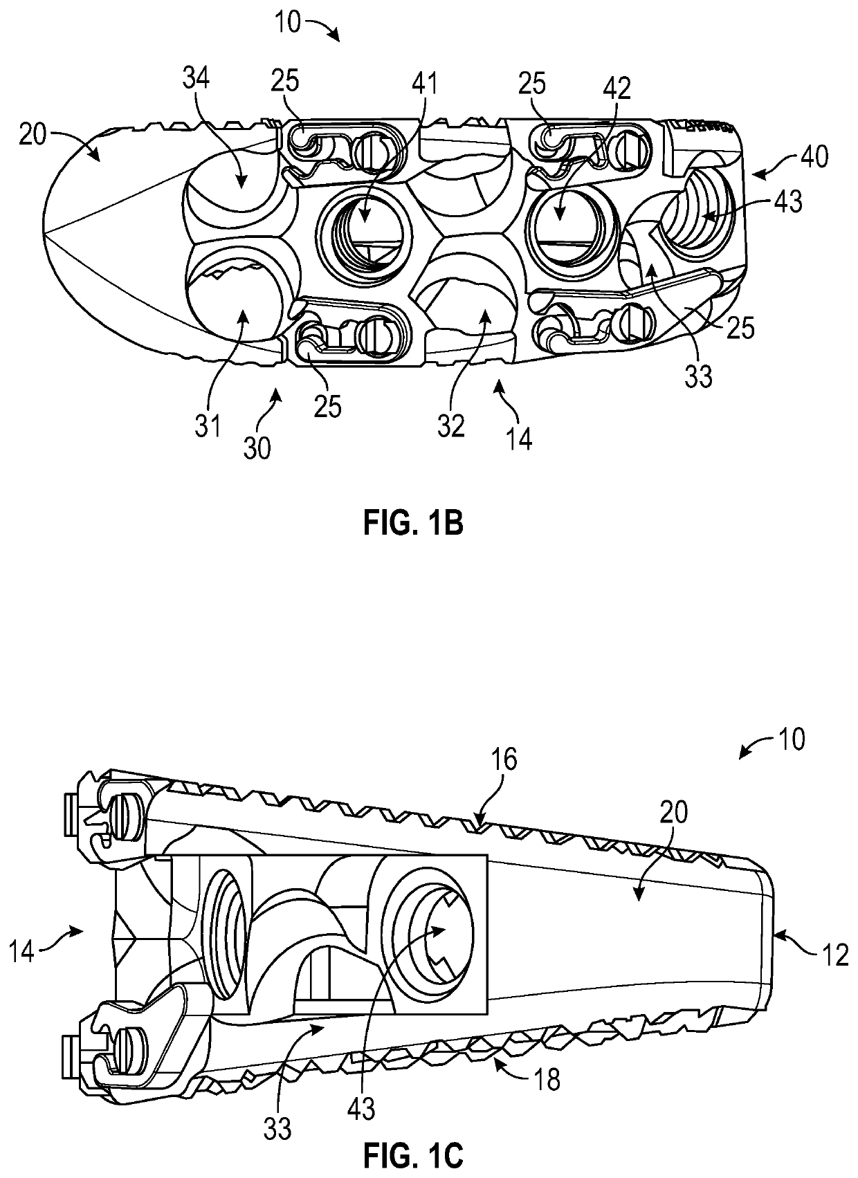
[0033]The present disclosure provides for a spinal interbody fusion device for use in a plurality of spinal surgical approaches. The device includes an interbody cage which is substantially oval and substantially hollow, having two sides representing width and two sides representing length of the cage. the cage is illustrated in FIGS. 1A, 1B, and 1C. As shown in FIGS. 1A, 1B, and 1C an interbody cage 10, includes a back 12, front 14, top 16, and bottom 18. Also shown in FIGS. 1A and 1B are clips 25. The cage 10 includes two or more holes along its outer surface 20, which travel through all or a portion of the cage 10 into an interior 22. In the first exemplary embodiment as shown in FIGS. 1A, 1B, and 1C, the cage 10 includes at least one hole 30, 40 on one side representing a width, and at least one hole 30, 40 on one side representing a length. Placement of at least one hole 30, 40 in these locations allow for use of the implant device in multiple approaches using the same device (...
second embodiment
[0039]FIGS. 3A and 3B show an implant which may be used with the ALIF approach illustrating an exemplary screw use of the implant. The implant 110 shown in FIGS. 3A and 3B includes a back 112, front 114, and outer surface 120. Exemplary screws are shown in fixation holes 131, 132, 134, and 135, with screw 151 in hole 131, screw 152 in hole 132, screw 154 in hole 134, and screw 155 in hole 135. Inserter holes 141, 142, and 143 and clips 125 are also shown in FIGS. 3A and 3B.
third embodiment
[0040]FIGS. 4A and 4B show an implant which may be used with the AL-ALIF approach illustrating an exemplary screw use of the implant. The implant 210 shown in FIGS. 4A and 4B includes a back 212, front 214, and outer surface 220. Exemplary screws are shown in fixation holes 232 and 235, with screw 252 in hole 232 and screw 255 in hole 235. Inserter holes 241, 242, and 243 and clips 225 are also shown in FIGS. 4A and 4B.
PUM
 Abstract
Description
Claims
Application Information
 - R&D
- Intellectual Property
- Life Sciences
- Materials
- Tech Scout
- Unparalleled Data Quality
- Higher Quality Content
- 60% Fewer Hallucinations
Browse by: Latest US Patents, China's latest patents, Technical Efficacy Thesaurus, Application Domain, Technology Topic, Popular Technical Reports.
© 2025 PatSnap. All rights reserved.Legal|Privacy policy|Modern Slavery Act Transparency Statement|Sitemap|About US| Contact US: help@patsnap.com


