
Interbody cage device and methods of use

a cage device and cage technology, applied in the field of implants used in spinal surgical procedures, can solve the problems of no method of selecting the size of the interbody fusion device which enables a controlled decompression, no method of approaching the spine of a patient for spinal interbody fusion or total disc replacement,

Active Publication Date: 2022-02-03
NOVAPPROACH SPINE
View PDF3 Cites 0 Cited by
  • Summary
  • Abstract
  • Description
  • Claims
  • Application Information

AI Technical Summary

Benefits of technology

The present patent is about an implant used in spinal surgical procedures and methods for selecting the size of the implant. The patent describes various embodiments of the implant and instrumentation for inserting it. The technical effects of the patent include providing a more efficient and controlled method for decompressing nerves and restoring spinal alignment, as well as a method for approaching the spine in a more minimally invasive way. The patent also describes various methods for selecting the size of the implant and surgically approaching the spine for interbody fusion or total disc replacement.

Problems solved by technology

In addition, there presently exists no method of selecting the size of an interbody fusion device which enables a controlled decompression of the nerves and restoration of the proper spinal alignment.
In addition, there presently exists no method of approaching the spine of a patient for spinal interbody fusion or total disc replacement through the oblique corridor which enables the patient to be positioned on the operating table in the supine position.

Method used


Image

  • Interbody cage device and methods of use
  • Interbody cage device and methods of use
  • Interbody cage device and methods of use

Examples


first embodiment

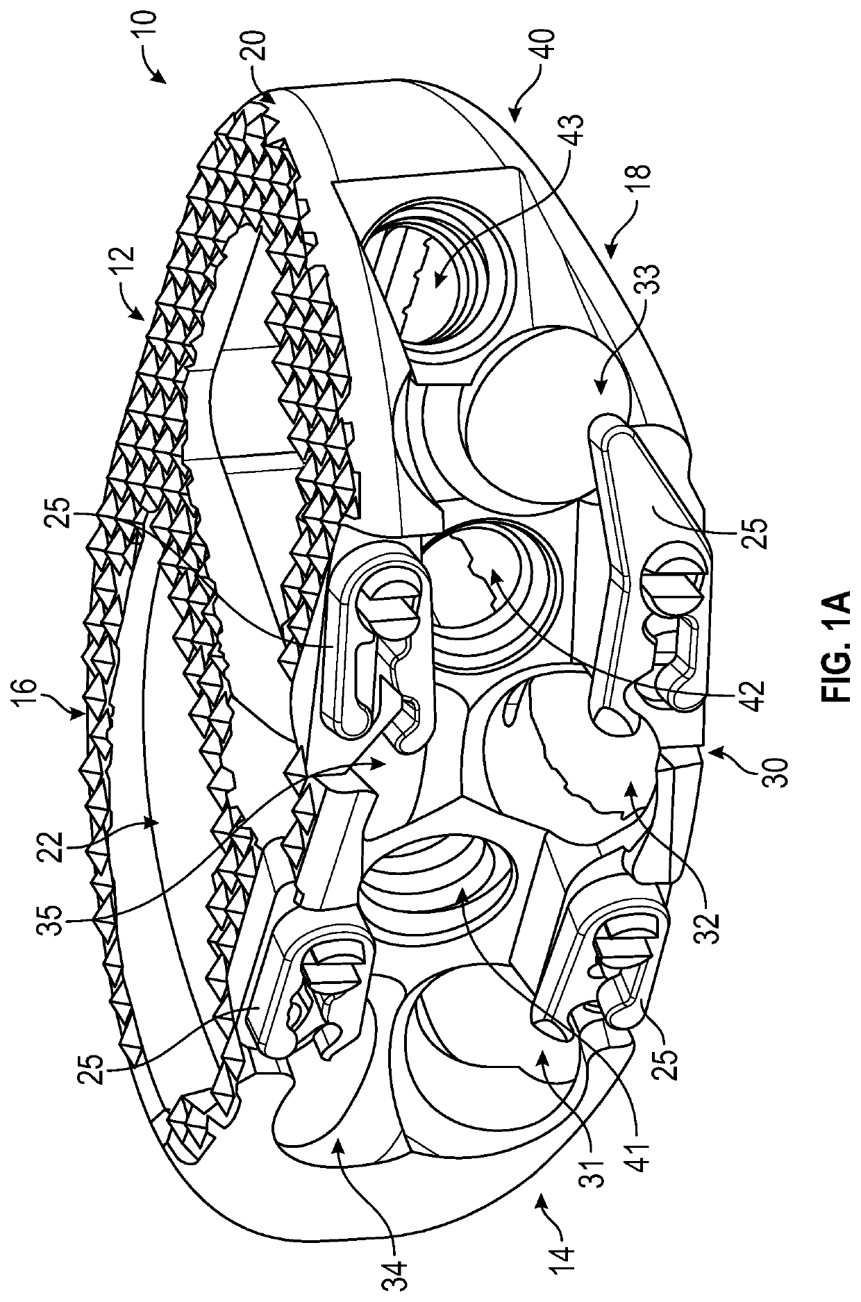
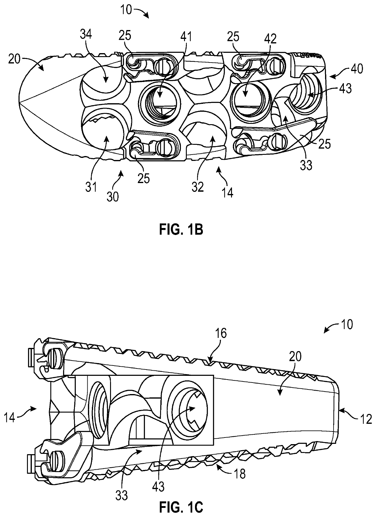
[0033]The present disclosure provides for a spinal interbody fusion device for use in a plurality of spinal surgical approaches. The device includes an interbody cage which is substantially oval and substantially hollow, having two sides representing width and two sides representing length of the cage. the cage is illustrated in FIGS. 1A, 1B, and 1C. As shown in FIGS. 1A, 1B, and 1C an interbody cage 10, includes a back 12, front 14, top 16, and bottom 18. Also shown in FIGS. 1A and 1B are clips 25. The cage 10 includes two or more holes along its outer surface 20, which travel through all or a portion of the cage 10 into an interior 22. In the first exemplary embodiment as shown in FIGS. 1A, 1B, and 1C, the cage 10 includes at least one hole 30, 40 on one side representing a width, and at least one hole 30, 40 on one side representing a length. Placement of at least one hole 30, 40 in these locations allow for use of the implant device in multiple approaches using the same device (...

second embodiment

[0039]FIGS. 3A and 3B show an implant which may be used with the ALIF approach illustrating an exemplary screw use of the implant. The implant 110 shown in FIGS. 3A and 3B includes a back 112, front 114, and outer surface 120. Exemplary screws are shown in fixation holes 131, 132, 134, and 135, with screw 151 in hole 131, screw 152 in hole 132, screw 154 in hole 134, and screw 155 in hole 135. Inserter holes 141, 142, and 143 and clips 125 are also shown in FIGS. 3A and 3B.

third embodiment

[0040]FIGS. 4A and 4B show an implant which may be used with the AL-ALIF approach illustrating an exemplary screw use of the implant. The implant 210 shown in FIGS. 4A and 4B includes a back 212, front 214, and outer surface 220. Exemplary screws are shown in fixation holes 232 and 235, with screw 252 in hole 232 and screw 255 in hole 235. Inserter holes 241, 242, and 243 and clips 225 are also shown in FIGS. 4A and 4B.


PUM


Abstract

A spinal interbody fusion device for use in a plurality of surgical approaches includes a cage, a top end, a bottom end, and at least a first side representing the width of the cage and at least a second side representing a length of the cage. The cage includes fixation holes and inserter holes, with each fixation hole being configured for accepting a screw or anchor and each inserter hole being accessible for one or more surgical approaches for performing a spinal fusion. Also included are methods for selecting a size of an intervertebral implant and methods of surgically approaching a spine of a patient for spinal surgical procedures.

Description

CROSS REFERENCE TO RELATED APPLICATION[0001]This application claims the benefit of the filing date of U.S. Provisional Patent Application No. 63 / 059,160, filed Jul. 30, 2020, the disclosure of which is incorporated, in its entirety, by this reference.FIELD OF THE INVENTION[0002]The present disclosure generally relates to implants used in spinal surgical procedures in a human. More particularly, the disclosure generally relates to implants used for implant and / or fusion and its methods of use and implantation approach.BACKGROUND OF THE INVENTION[0003]The treatment of disorders to the spine has advanced over the years to be adapted to to address many forms of spinal disorders. Multiple surgical approaches exist to treat spinal disorders, including Anterior Lumbar Interbody Fusion (a.k.a. ALIF), Oblique Lumbar Interbody Fusion / Anterior to Psoas (a.k.a. OLIF / ATP) and Direct Lateral Interbody Fusion / Extreme Lateral Interbody Fusion (a.k.a. DLIF, XLIF), to name a few. However, with each a...

Claims


Application Information

Patent Timeline
IPC IPC(8): A61F2/44A61F2/46A61F2/30
CPCA61F2/446A61F2/4611A61F2/30771A61F2/4657A61F2002/30784A61F2002/30158A61F2002/30537A61F2002/4658A61F2002/3085A61F2/30749A61F2/4455A61F2/447A61F2002/30266A61F2002/30331A61F2002/30398A61F2002/30405A61F2002/30471A61F2002/30507A61F2002/30528A61F2002/30538A61F2002/30556A61F2002/30624A61F2002/4622A61F2002/4625A61F2002/4627
Inventor CLOUTIER, RAYMONDBERVEN, SIGURDMACMILLAN, MICHAELTERRAMANI, THOMAS
Owner NOVAPPROACH SPINE
Learn More