
Hinge structure of button and electronic device

a button and electronic device technology, applied in the direction of emergency actuators, electrical apparatus casings/cabinets/drawers, casings with display/control units, etc., can solve the problems of easy wobble of buttons and easy worsening of pressing sensation when the button is pressed

Pending Publication Date: 2021-12-30
JVC KENWOOD CORP A CORP OF JAPAN
View PDF5 Cites 1 Cited by
  • Summary
  • Abstract
  • Description
  • Claims
  • Application Information

AI Technical Summary

Benefits of technology

The present invention provides a hinge structure for a button and an electronic device that reduces the wobbling of the button and minimizes the reactive force when it is pressed.

Problems solved by technology

Thus, when the button is pressed, there is concern that the button easily wobbles.
In this case, there is concern that pressing feeling felt when the button is pressed easily worsens.

Method used


Image

  • Hinge structure of button and electronic device
  • Hinge structure of button and electronic device
  • Hinge structure of button and electronic device

Examples


embodiment

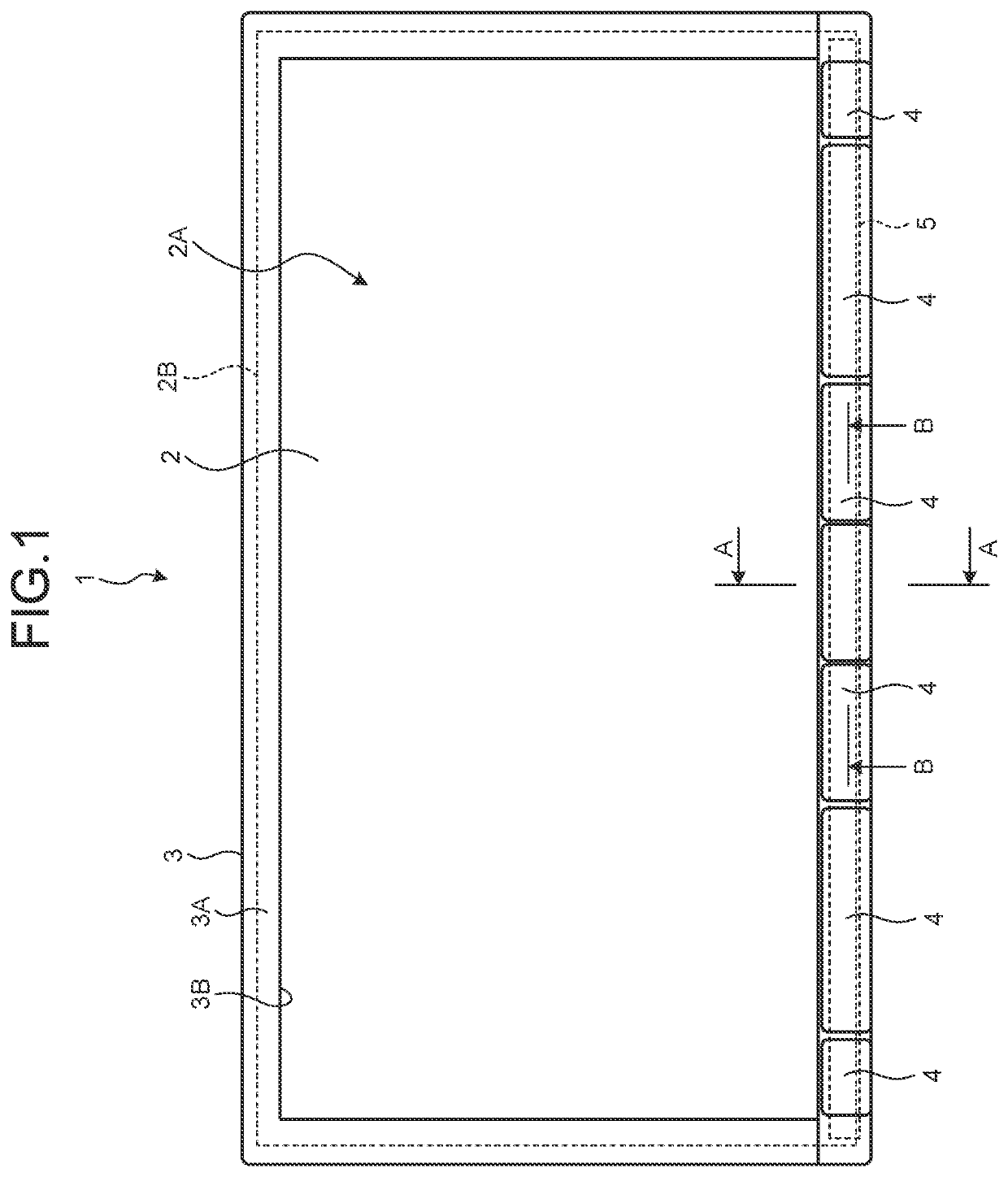
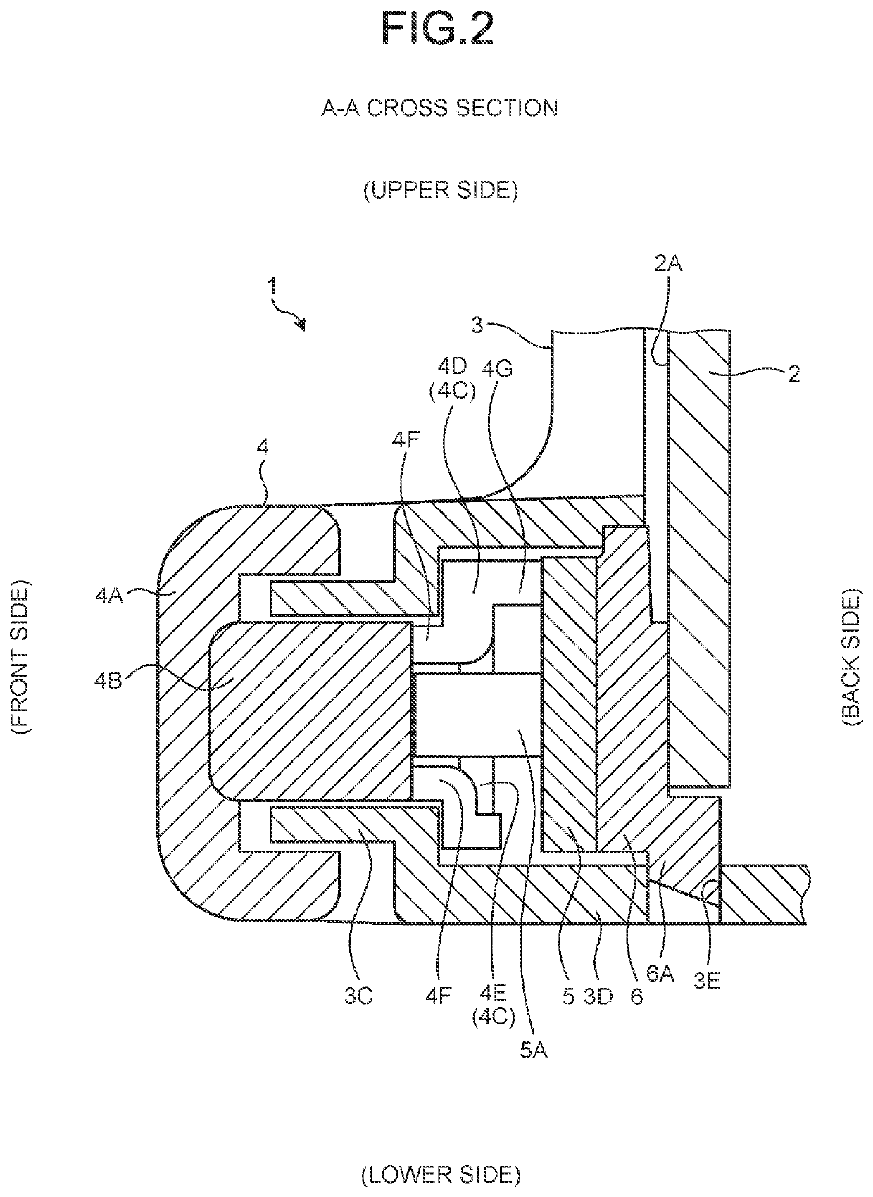
[0014]FIG. 1 is a front view illustrating an electronic device 1 according to an embodiment. FIG. 2 is a cross-sectional view taken along an A-A line in FIG. 1. As illustrated in FIGS. 1 and 2, the electronic device 1 according to the present embodiment is an audio visual (AV) integrated car navigation device mounted inside a vehicle, for example. The electronic device 1 includes a display panel 2, a front panel 3, a button 4, a substrate 5, and a holder unit 6.

[0015]Note that, in the following description, an upper side in normal use of the electronic device 1 will be described as an upper side also in the electronic device 1, and a lower side in normal use of the electronic device 1 will be described as a lower side also in the electronic device 1. In addition, in the following description, a horizontal direction when the electronic device 1 is viewed from the front panel 3 side will be described as a horizontal direction also in the electronic device 1.

[0016]The display panel 2 i...

modified example

[0046]Note that, in the above-described embodiment, the first hinges 4D arranged on the both end sides in the longer direction of the button main body 4B are coupled to the button main body 4B on the same side in the shorter direction of the button main body 4B, but the first hinges 4D arranged on the both end sides of the button main body 4B may be coupled to mutually different sides in the shorter direction of the button main body 4B. In addition, in the above-described embodiment, the side on which the first hinges 4D are coupled to the button main body 4B, and the side on which the second hinges 4E are coupled to the button main body 4B in the shorter direction of the button main body 4B become the same in all of the plurality of buttons 4, but sides to which the first hinge 4D and the second hinge 4E are coupled may vary among the buttons 4. It is preferable that a side on which the first hinge 4D or the second hinge 4E is coupled to the button main body 4B in the shorter direc...


PUM


Abstract

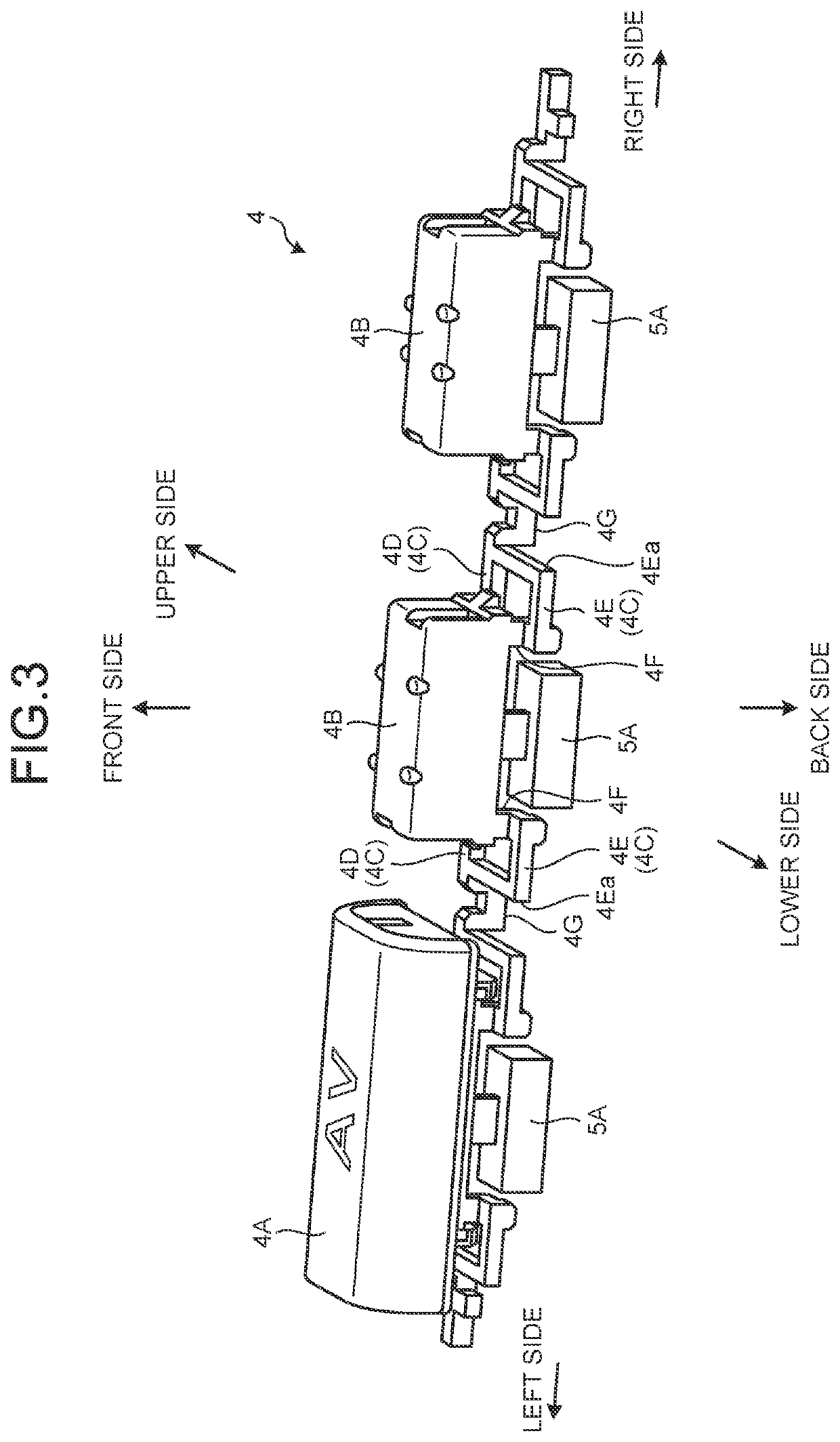
For suppressing wobbling of a button while suppressing reactive force generated when the button is pressed, a hinge structure of a button includes a contact portion contacting a substrate on which the button is arranged, a button main body varying in a relative positional relationship with the substrate, a first hinge having flexibility, and being coupled to the button main body at one end and coupled to the contact portion at another end, and a second hinge having flexibility, and being coupled at one end to a position in the button main body on an opposite side on which the first hinge is coupled to the button main body, and coupled at another end to the first hinge at a position in the button main body on a side on which the first hinge is coupled.

Description

CROSS-REFERENCE TO RELATED APPLICATION[0001]This application is a Continuation of PCT International Application No. PCT / JP2019 / 040498 filed on Oct. 15, 2019 which claims the benefit of priority from Japanese Patent Application No. 2019-057481 filed on Mar. 25, 2019, the entire contents of both of which are incorporated herein by reference.BACKGROUND1. Technical Field[0002]The present disclosure relates to a hinge structure of a button, and an electronic device.2. Description of the Related Art[0003]Push-type buttons for performing input operations by being pressed by a user include a button that is supported by an elastically-deforming hinge, and can be pressed by the hinge elastically deforming. For example, JP 2000-123669 A discloses supporting one end portion of a button in a longer direction by a hinge, and JP 2000-306461 A discloses supporting both end sides of a button in the longer direction by a hinge.[0004]Nevertheless, in a case where one end portion of the button in the l...

Claims


Application Information

Patent Timeline
Patent Type & Authority Applications(United States)
IPC IPC(8): H01H13/20H05K5/00H01H13/14
CPCH01H13/20H01H13/14H05K5/0017H01H13/7065H01H13/84H01H2221/044H01H2221/058H01H2221/062
Inventor SHIMOYAMA, TAKESHI
Owner JVC KENWOOD CORP A CORP OF JAPAN
Learn More