Lidar device

Pending Publication Date: 2021-12-16
YEUN YONG HYUN
View PDF8 Cites 0 Cited by
  • Summary
  • Abstract
  • Description
  • Claims
  • Application Information

AI Technical Summary

Benefits of technology

[0014]According to the present invention, by integrating the transmission mirror and the reception mirror and utilizing the conventional unused shaded area as the optical transmission area, there is an advantage in that it is possible to minimize the design of the lidar device because the separate optical transmission space is unnecessary.
[0015]In addition, according to the present invention, by adopting the mirror structure instead

Problems solved by technology

In addition, in order to implement a wide FOV, an expensive wide-angle lens should be used for the transmission optical system and the

Method used


Image

  • Lidar device
  • Lidar device
  • Lidar device

Examples


Example

BEST MODE

[0022]Hereinafter, a lidar device according to the present device will be described in detail with reference to the accompanying drawings. The accompanying drawings are provided by way of example in order to sufficiently transfer the spirit of the present invention to those skilled in the art, and the present invention is not limited to the accompanying drawing provided below, but may be implemented in other forms.

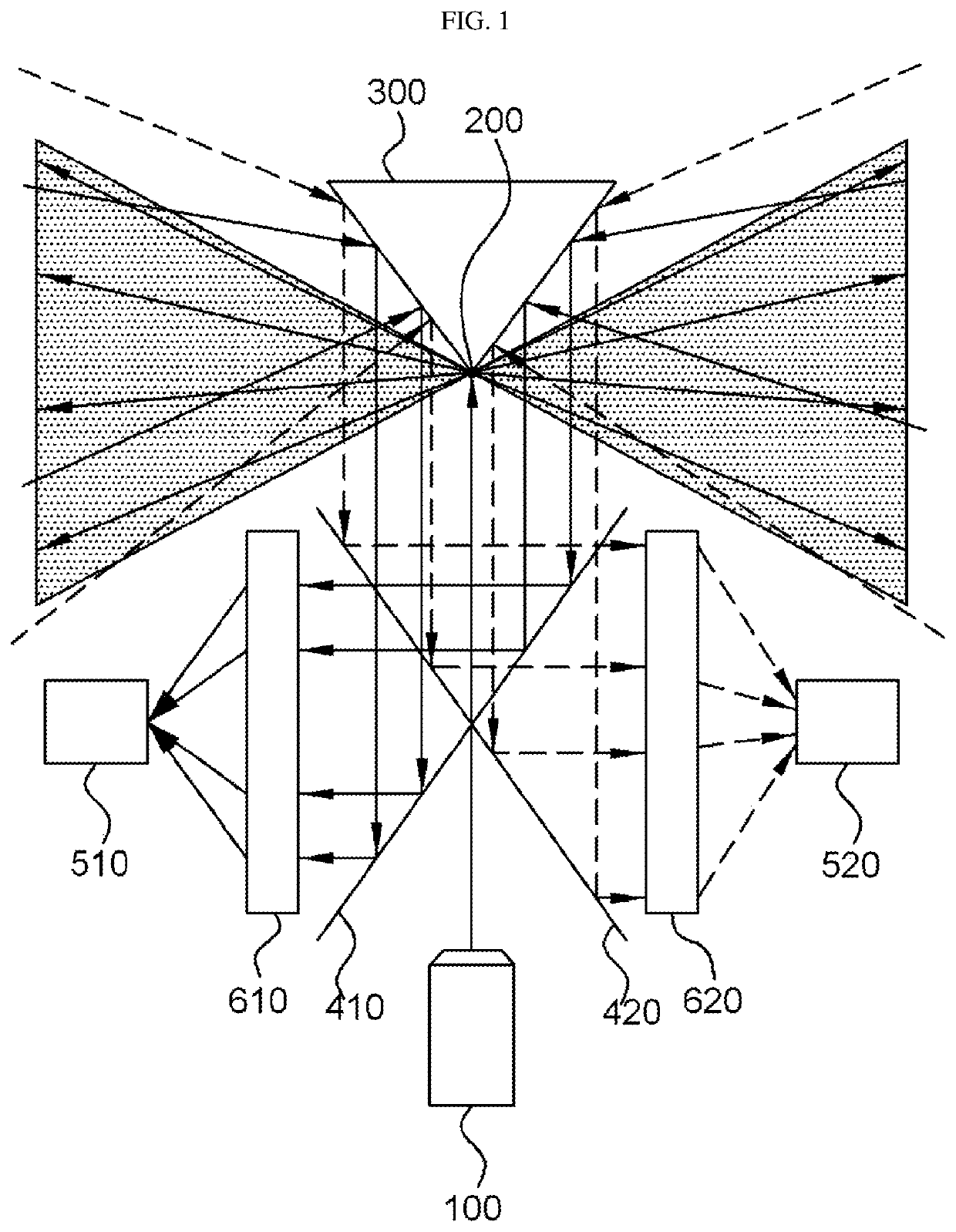
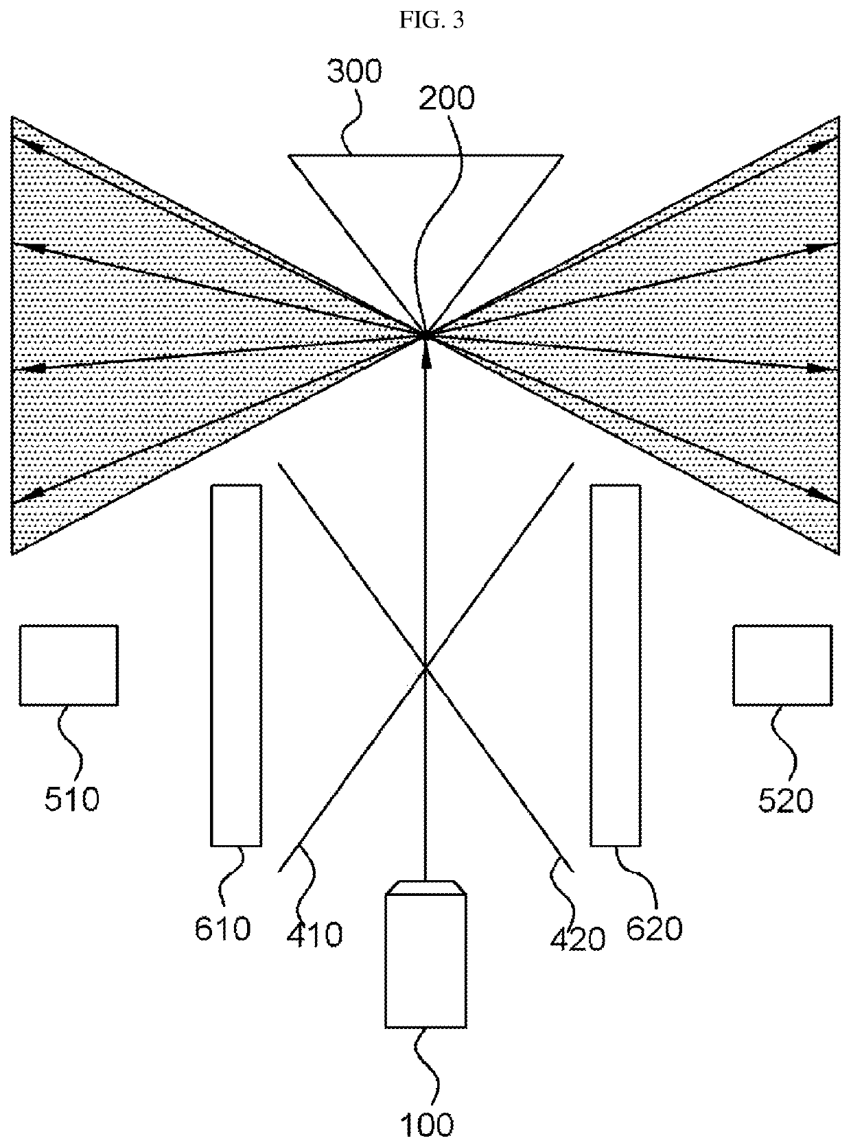
[0023]When a lidar device according to the present invention emits light of a predetermined wavelength band and the light of the predetermined wavelength band is then reflected by an external object, the lidar device receives the reflected light of the predetermined wavelength band to measure a distance of the external object.

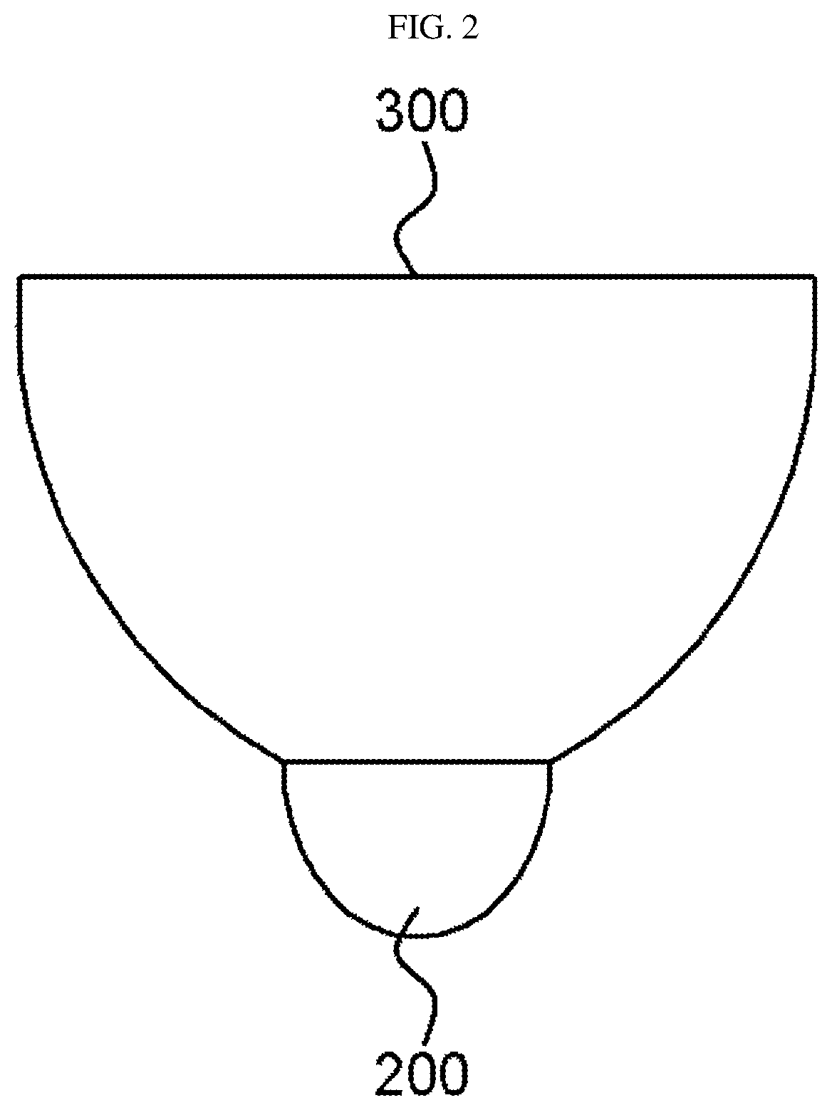
[0024]Referring to FIGS. 1 and 2, a lidar device according to an exemplary embodiment of the present invention may include a light source 100, a transmission mirror 200, a reception mirror 300, a first mirror 410, a second mirror 420, a light...


PUM


Abstract

The present invention relates to a lidar device for measuring a distance of an external object using light. According to the present invention, the transmission mirror and the reception mirror are integrally formed, and a shadow region, which has not been conventionally used, is utilized as a light transmission region such that a separate light transmission space is unnecessary, thereby enabling a minimized design of the lidar device.

Description

TECHNICAL FIELD[0001]The present invention relates to a lidar device for measuring a distance of an external object using light.BACKGROUND ART[0002]Light detection and ranging (LiDAR) refers to measuring a distance by detecting a time of flight or a phase difference of light received from an external object after illuminating the external object with light.[0003]The lidar is similar to radio detection and ranging (RADAR) which uses radio waves in a measuring method, but there is a difference in that the lidar uses light instead of the radio waves, and for this reason, the lidar is also called ‘image radar’. In addition, the lidar has characteristics of superior spatial resolution and resolution compared to the radar.[0004]In addition, the lidar is also utilized as an application to measure various physical properties such as atmosphere velocity or component analysis using light.[0005]With the recent remarkable development in laser optics and semiconductor processes, the lidar, which...

Claims


Application Information

Patent Timeline
IPC IPC(8): G01S7/481G01S17/89
CPCG01S7/4811G01S17/89G01S17/894
Inventor YEUN, YONG-HYUN
Owner YEUN YONG HYUN
Why Eureka
Try Eureka