
Fast robot motion optimization with distance field

a robot and distance field technology, applied in the field of industrial robot motion control, can solve the problems of reducing the efficiency so as to reduce the objective function, and reduce the difficulty of robot arm operation

Active Publication Date: 2021-10-07
FANUC LTD
View PDF4 Cites 8 Cited by
  • Summary
  • Abstract
  • Description
  • Claims
  • Application Information

AI Technical Summary

Benefits of technology

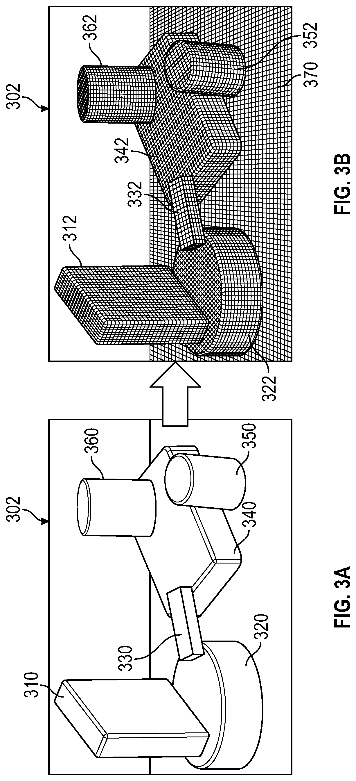
The present patent is about a technique for avoiding collisions between a robot and obstacles in its workspace using a distance field constraint function. The technique converts CAD or sensor data to voxels and creates a 3D binary matrix of voxel occupancy. A corresponding 3D distance field matrix is computed, which contains a distance to a nearest cell occupied by an obstacle voxel. This distance field matrix is used as a constraint function in a motion planning optimization problem, which is solved to yield a robot motion profile that avoids the obstacles and minimizes the objective function. The technique is easy to set up and requires no creation of geometry primaries. It is quickly computed and its computation time is independent of the number of obstacles.

Problems solved by technology

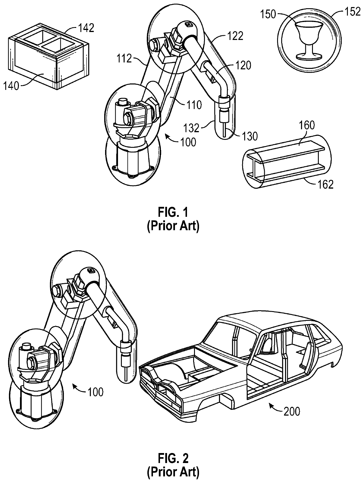
In many robot workspace environments, obstacles are present and may be in the path of the robot's motion.
A large workpiece which is being operated on by the robot may itself be an obstacle, as the robot must maneuver in or around the workpiece while performing an operation such as welding.
However, defining the geometry primitives around each obstacle and each robot arm is a tedious and time-consuming process.
Furthermore, some objects, such as a vehicle body which is being welded or painted by the robot, do not lend themselves well to approximation using geometry primitives.
Another problem with prior art techniques for collision avoidance robot motion planning is that computation time for the optimization problem increases dramatically with the number of obstacles.
If more than a few obstacles exist in the robot's workspace, the motion planning computation takes too long to be practical in an environment where collision avoidance calculations must be performed in real time as the robot operates.

Method used


Image

  • Fast robot motion optimization with distance field
  • Fast robot motion optimization with distance field
  • Fast robot motion optimization with distance field

Examples


Embodiment Construction

[0019]The following discussion of the embodiments of the disclosure directed to a robot collision avoidance motion optimization technique using a distance field constraint function is merely exemplary in nature, and is in no way intended to limit the disclosed devices and techniques or their applications or uses.

[0020]It is well known to use industrial robots for a variety of manufacturing, assembly and material movement operations. In many robot workspace environments, obstacles are present and may be in the path of the robot's motion—that is, the obstacles may be located between where a robot is currently positioned and the robot's destination position. The obstacles may be permanent structures such as machines and fixtures, or the obstacles may be temporary or mobile. A large workpiece which is being operated on by the robot may itself be an obstacle, as the robot must maneuver in or around the workpiece while performing an operation such as welding. Techniques have been develope...


PUM


Abstract

A robot collision avoidance motion optimization technique using a distance field constraint function. CAD or sensor data depicting obstacles in a robot workspace are converted to voxels, and a three-dimensional binary matrix of voxel occupancy is created. A corresponding distance map matrix is then computed, where each cell in the distance map matrix contains a distance to a nearest occupied cell. The distance map matrix is used as a constraint function in a motion planning optimization problem, where the optimization problem is convexified and then iteratively solved to yield a robot motion profile which avoids the obstacles and minimizes an objective function such as distance traveled. The distance field optimization technique is quickly computed and has a computation time which is independent of the number of obstacles. The disclosed optimization technique is easy to set up, as it requires no creation of geometry primitives to approximate robot and obstacle shapes.

Description

BACKGROUNDField[0001]The present disclosure relates to the field of industrial robot motion control and, more particularly, to a robot collision avoidance motion planning technique which converts obstacle data to voxels, creates a three-dimensional binary matrix of occupied and unoccupied voxels, and computes a distance map in which each cell contains a distance to a nearest occupied cell, then uses the distance map as a constraint in a motion optimization calculation to compute a most efficient robot arm path which avoids the obstacles.Discussion of the Related Art[0002]The use of industrial robots to perform a wide range of manufacturing, assembly and material movement operations is well known. In many robot workspace environments, obstacles are present and may be in the path of the robot's motion. The obstacles may be permanent structures such as machines and fixtures, or the obstacles may be temporary or mobile. A large workpiece which is being operated on by the robot may itsel...

Claims


Application Information

Patent Timeline
IPC IPC(8): B25J9/16
CPCB25J9/1605B25J9/1697B25J9/1666B25J9/1651B25J13/087G05B2219/35145
Inventor LIN, HSIEN-CHUNGKATO, TETSUAKI
Owner FANUC LTD
Learn More