
Wavelength conversion element, light source device, and projector

Active Publication Date: 2021-09-23
SEIKO EPSON CORP
View PDF0 Cites 0 Cited by
  • Summary
  • Abstract
  • Description
  • Claims
  • Application Information

AI Technical Summary

Benefits of technology

The present patent describes a wavelength conversion element that can convert light in one color to another color. It includes a layer with a scattering element that is no higher than 5% in volume ratio. The element includes multiple protruding parts that are opposed to its surface and are at least 1 μm tall with a distance between their vertices of at least 3 μm. A light source device and a projector that use this element are also described. The technical effects of this invention include improved color conversion and reduced scattering, which enhance the quality and precision of color applications such as displays and projectors.

Problems solved by technology

However, when using the wavelength conversion layer including little scattering elements, it is difficult to extract the fluorescence generated in the wavelength conversion layer, and there is a possibility that the use efficiency of the fluorescence decreases.

Method used


Image

  • Wavelength conversion element, light source device, and projector
  • Wavelength conversion element, light source device, and projector
  • Wavelength conversion element, light source device, and projector

Examples


first embodiment

Advantages of First Embodiment

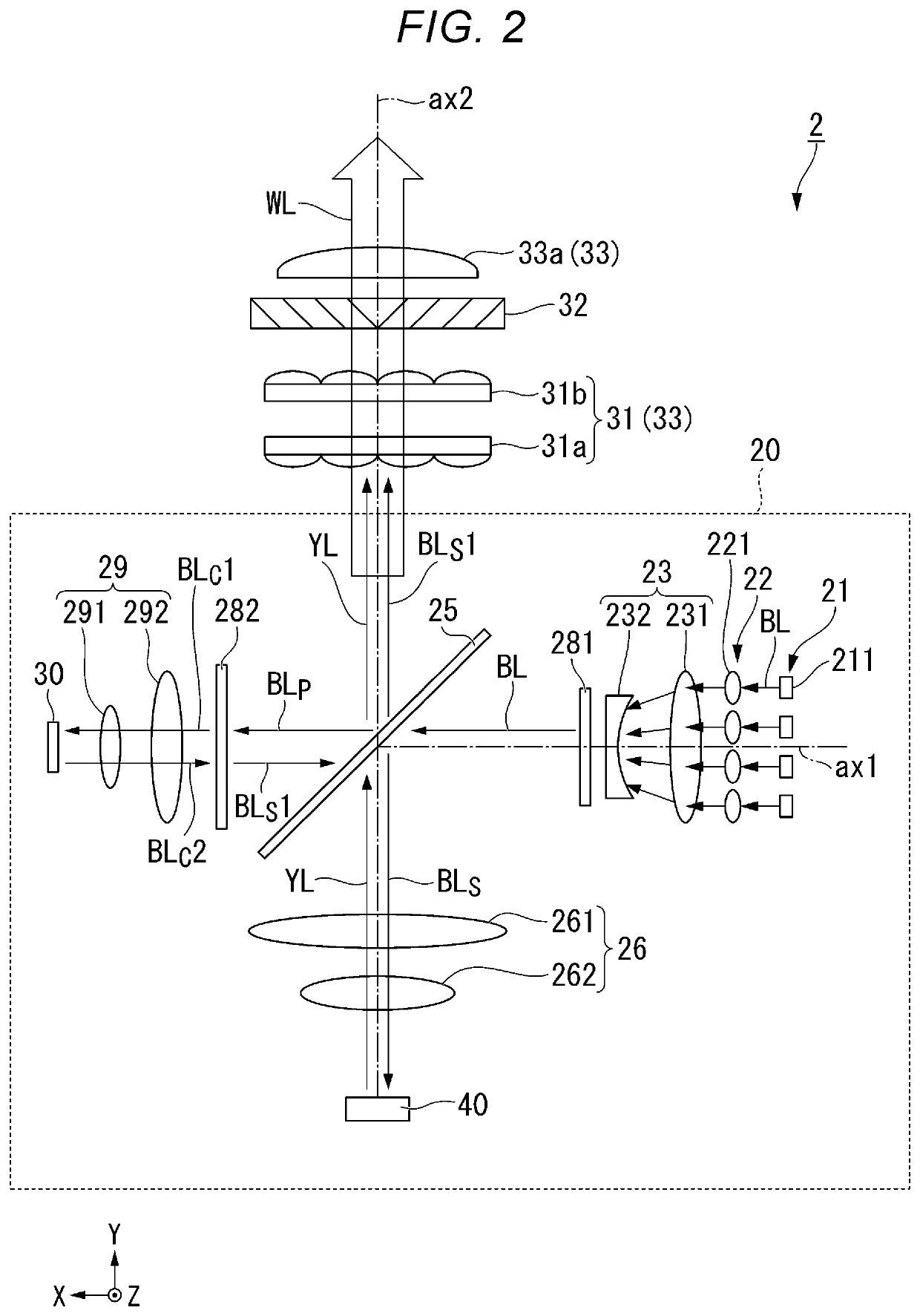
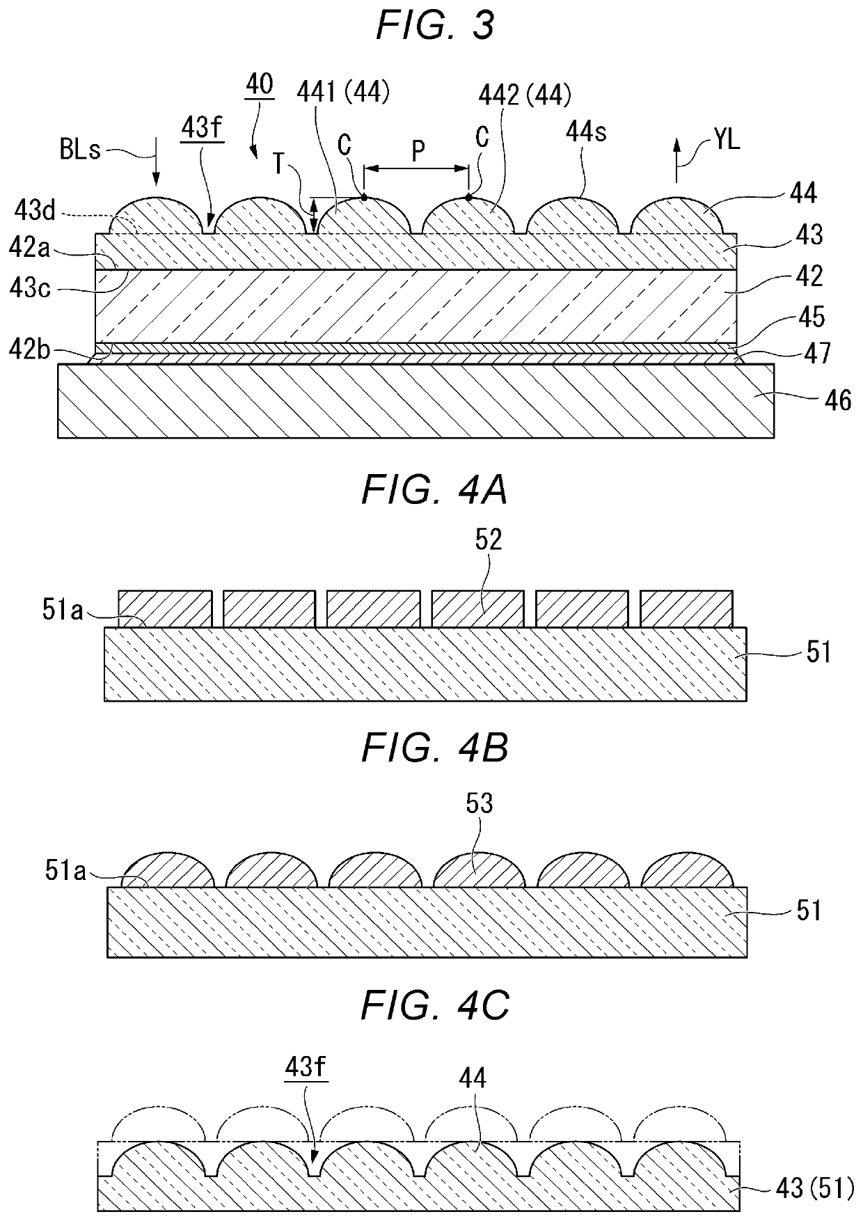
[0111]The wavelength conversion element 40 according to the present embodiment is provided with the wavelength conversion layer 42 and the plurality of protruding parts 44, wherein the wavelength conversion layer 42 has the first surface 42a and the second surface 42b different from the first surface 42a, includes the scattering element no higher than 5% in volume ratio, and converts the blue light beams BLs into the fluorescence YL, the plurality of protruding parts 44 is disposed so as to be opposed to the first surface 42a, and includes the first protruding part 441 and the second protruding part 442 adjacent to each other, and the height T of the protruding parts 44 is no smaller than 1 μm and the pitch P of the protruding parts 44 is no smaller than 3 μm.

[0112]According to this configuration, by disposing the plurality of protruding parts 44 so as to be opposed to the first surface 42a of the wavelength conversion layer 42, it is possible to effici...

second embodiment

Advantages of Second Embodiment

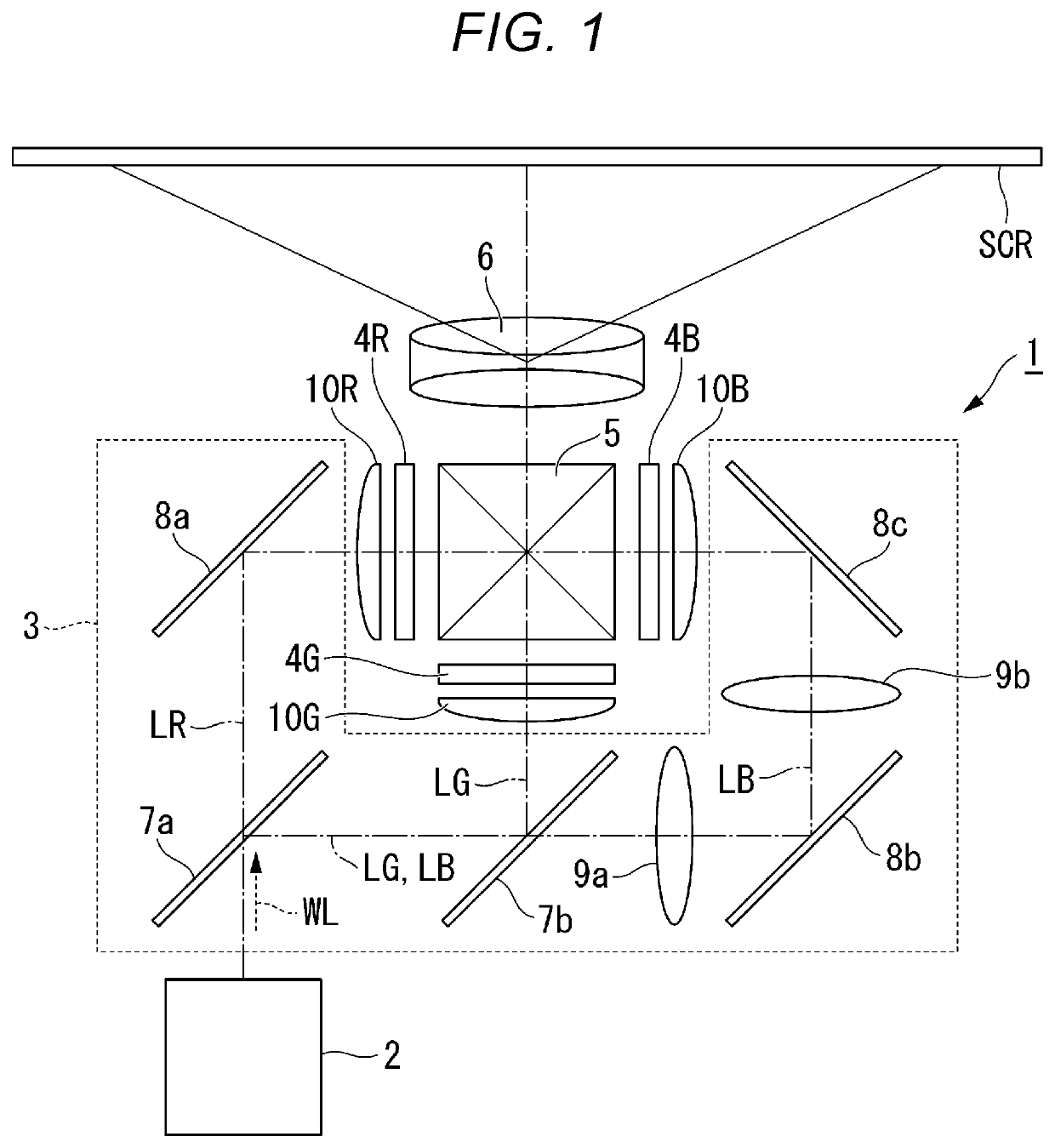
[0144]Also in the present embodiment, it is possible to obtain substantially the same advantages as those of the first embodiment such as the advantage that it is possible to realize the wavelength conversion element 60 excellent in use efficiency of the fluorescence, the advantage that it is possible to suppress the loss of the excitation light and at the same time it is possible to increase the thermal conductivity of the wavelength conversion layer 42 to thereby increase the wavelength conversion efficiency, and the advantage that it is possible to realize the light source device 20 and the projector 1 high in efficiency.

[0145]Further, in the wavelength conversion element 60 according to the present embodiment, the substrate part 63 and the plurality of protruding parts 64 are formed of the thin film 66. Therefore, in the manufacturing process, it is possible to omit the process of bonding the light transmissive substrate and the phosphor substrate ...

third embodiment

Advantages of Third Embodiment

[0156]Also in the present embodiment, it is possible to obtain substantially the same advantages as those of the first embodiment such as the advantage that it is possible to realize the wavelength conversion element 70 excellent in use efficiency of the fluorescence, the advantage that it is possible to suppress the loss of the excitation light and at the same time it is possible to increase the thermal conductivity of the wavelength conversion layer 42 to thereby increase the wavelength conversion efficiency, and the advantage that it is possible to realize the light source device 20 and the projector 1 high in efficiency.

[0157]When the first surface 42a of the wavelength conversion layer 42 is provided with the convex-lens shaped structures, there is a possibility that the blue light beams BLs are focused inside the wavelength conversion layer 42 due to the condensing effect of the convex lens, and the wavelength conversion efficiency decreases due t...


PUM


Abstract

The wavelength conversion element according to the present disclosure includes a wavelength conversion layer which has a first surface and a second surface different from the first surface, and which includes a scattering element no higher than 5% in volume ratio, and which is configured to convert light in a first wavelength band into light in a second wavelength band different from the first wavelength band, and a plurality of protruding parts which is disposed so as to be opposed to the first surface, and which includes a first protruding part and a second protruding part adjacent to each other. A height of the plurality of protruding parts is no smaller than 1 μm, and a distance between a vertex of the first protruding part and a vertex of the second protruding part in a direction along the first surface is no smaller than 3 μm.

Description

[0001]The present application is based on, and claims priority from JP Application Serial Number 2020-047574, filed Mar. 18, 2020, the disclosure of which is hereby incorporated by reference herein in its entirety.BACKGROUND1. Technical Field[0002]The present disclosure relates to a wavelength conversion element, a light source device, and a projector.2. Related Art[0003]As a light source device used for a projector, there is proposed a light source device using fluorescence emitted from a phosphor when irradiating the phosphor with excitation light emitted from a light emitting element. In JP-A-2017-215549 (Document 1), there is disclosed a wavelength conversion element having a first reflecting layer, a wavelength conversion layer, a second reflecting layer, and a light scattering layer stacked on one surface of a substrate in this order from the substrate side.[0004]In the wavelength conversion element in Document 1, closer to the incident side of the excitation light than the wa...

Claims


Application Information

Patent Timeline
IPC IPC(8): H04N9/31
CPCH04N9/3158H04N9/3152G03B21/204F21K9/64H04N9/3167H04N9/3141
Inventor YOTSUYA, SHINICHISHIMIZU, TETSUOKOIZUMI, RYUTAHIROKI, MIZUHA
Owner SEIKO EPSON CORP
Learn More