
Modeling and calculation aerodynamic performances of multi-stage transonic axial compressors

a technology of transonic axial compressor and aerodynamic performance, which is applied in the direction of air-flow influencers, instruments, transportation and packaging, etc., can solve the problems of narrower working range, increase structural load, and decrease in performance, and inherently complex design of axial compressors

Inactive Publication Date: 2021-07-08
VIETTEL GRP
View PDF2 Cites 9 Cited by
  • Summary
  • Abstract
  • Description
  • Claims
  • Application Information

AI Technical Summary

Benefits of technology

The invention provides a method for modeling and calculating the aerodynamic characteristics of multi-stage axial compressors using commercial software ANSYS CFX. The method takes into account the complex design and performance requirements of these compressors, which are widely used in aviation and energy industry. The invention aims to improve the performance and fuel economy of these engines by increasing the compression ratio of the axial compressor while balancing multiple factors such as structural load, performance, and emission control. The method involves modeling the object, creating a calculation model, and solving the problem in ANSYS CFX. The results analysis includes checking the accuracy of the model and optimizing the compressor design for specific performance requirements. The invention provides a reliable and efficient tool for designing and optimizing multi-stage axial compressors.

Problems solved by technology

However, increasing the compression ratio of axial compressor often causes an increase in structural load, decrease in performance as well as narrower working range, so the design needs to be balanced with many factors.
Meanwhile, designing axial compressor is inherently complex (large number of stage and input variables, high-performance requirement, stable working in many different conditions .
. . ), therefore compressor optimization is even more complicated.
By the 1960s, 1970s, the designing method of axial compressor was mainly prototype and experimental design, requiring a lot of time with high cost but not efficiency, especially in the design improving and optimizing process.
However, due to the complexity of modeling and calculating vane machine in general and axial compressor in particular, the calculation was only applied to the individual compression stage in the first period.

Method used


Image

  • Modeling and calculation aerodynamic performances of multi-stage transonic axial compressors
  • Modeling and calculation aerodynamic performances of multi-stage transonic axial compressors
  • Modeling and calculation aerodynamic performances of multi-stage transonic axial compressors

Examples


Embodiment Construction

[0011]First, identify keys parameters of an universal compressor model: inlet mass flow rate, pressure ratio, total to total isentropic efficiency, surge margin and flow distribution at design point and off-design. FIG. 2 shows an example of standard compressor performance map, this chart is a part of calculation results.

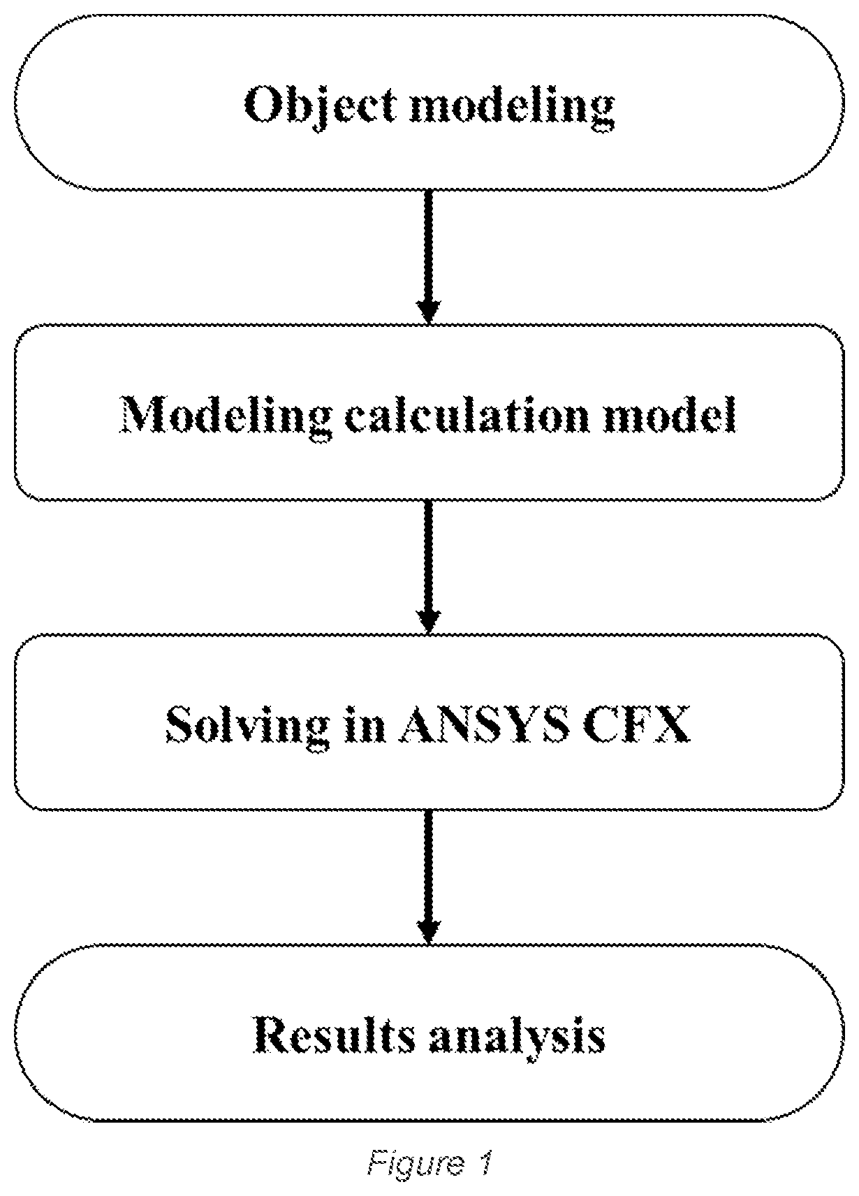
[0012]Method of modeling and calculating aerodynamic characteristics of multi-stage axial compressors includes the following steps: Step 1: Modeling object; Step 2: Modeling the calculation model; Step 3: Solving in ANSYS CFX; Step 4: Results analysis. More precisely, this calculation procedure includes following steps:

[0013]Step 1: Modeling Object

[0014]From the characteristics of jet engines and multi-stage axial compressor components, object modeling is built on the assumption: ignoring the gravity effect (since the influence of gravity is full time and is very small compared to other force components such as axial force, centrifugal force) and friction at the bea...


PUM


Abstract

This invention refers to the method of modeling and calculating aerodynamic characteristics of a multi-stage axial compressor using commercial software, method to identify the stable working range of module. The method includes step 1: object modeling; step 2: constructing the calculation model; step 3: problem solving. Step 4: results analysis.

Description

BACKGROUND OF THE INVENTION[0001]The invention refers to the method of modeling and calculating aerodynamic characteristics of a multi-stage axial compressor, equipped for jet engines. Since this type of engine is capable of providing many different power levels as well as a high thrust-to-weight and size ratio, they are widely used in the fields of aviation, maritime, energy industry and so on. Currently, with the development of science and technology, computer science in general, aviation, maritime together with energy industry are making great progress, widely applied in various military and civilian fields. Typically in the field of aviation, the flying equipment is constantly optimized to increase performance, reduce emission pollution, noise pollution, etc . . . . One of the key components is the engine—the equipment providing thrust and electric, pneumatic and hydraulic power to auxiliary systems. In the history of aviation development, many types of engines have been used su...

Claims


Application Information

Patent Timeline
IPC IPC(8): G06F30/15G06T17/20B64D33/02B64C21/02
CPCG06F30/15B64C21/02B64D33/02G06T17/20G06F30/20Y02T90/00
Inventor BUI, XUAN LONGNGUYEN, QUANG HAINGUYEN, TRUONG GIANGPHAM, VAN SON
Owner VIETTEL GRP
Learn More