Electric machine with noise-reducing rotor notches

Active Publication Date: 2021-06-17
GM GLOBAL TECH OPERATIONS LLC
View PDF0 Cites 4 Cited by
  • Summary
  • Abstract
  • Description
  • Claims
  • Application Information

AI Technical Summary

Benefits of technology

The patent text describes a new way to reduce noise in electric vehicles that use rotary electric machines. The text describes how the outer surface of the rotor is modified with arcuate notches that are symmetrically spaced for each rotor pole. These notches can help to reduce noise, vibration, and harshness in the vehicle without negatively impacting the motor's performance or efficiency. The size, shape, and position of the notches can be adjusted for different applications to maximize noise reduction and evenly distribute vibration energy throughout the motor. The use of tangentially-continuous fillets or other suitable transition contours can help to smoothly transition the notch into the outer surface of the rotor and avoid rotor stress concentration and noise. This approach can help to make electric vehicles quieter and more comfortable for drivers.

Problems solved by technology

Such machine noise tends to be most prevalent at dominant winding and torque ripple orders, for instance at three harmonics of a pole pass order for an exemplary three-phase electric machine.
However, such skewing techniques may have the undesirable effect of reducing overall machine performance and operating efficiency.

Method used


Image

  • Electric machine with noise-reducing rotor notches
  • Electric machine with noise-reducing rotor notches
  • Electric machine with noise-reducing rotor notches

Examples


Embodiment Construction

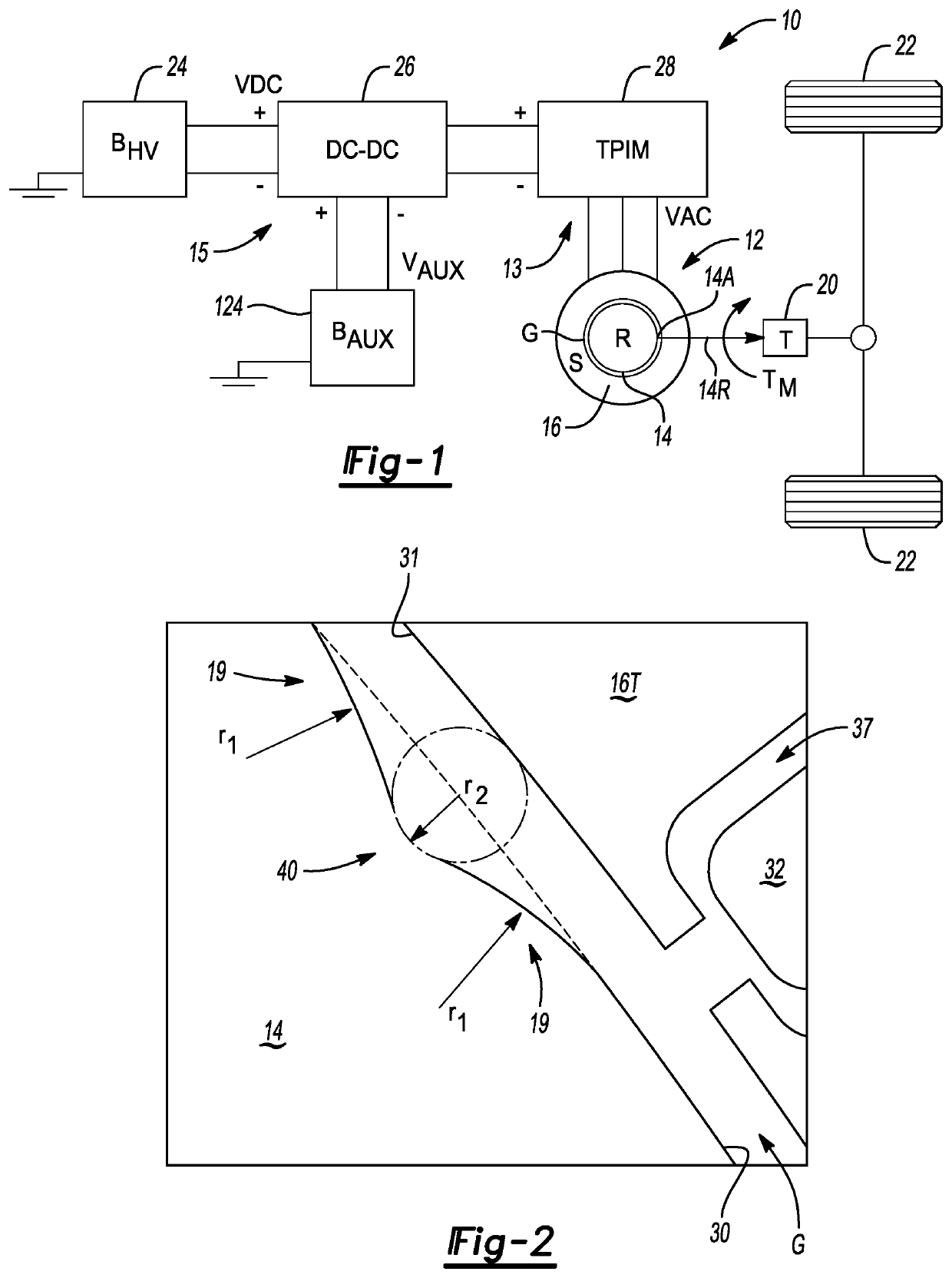
[0023]Referring to the drawings, wherein like reference numbers refer to the same or like components in the several Figures, an electrified powertrain 10 is depicted schematically in FIG. 1, e.g., for use aboard an exemplary motor vehicle 11. The powertrain 10 includes a rotary electric machine 12 having a rotor assembly 14A and a stator 16. When the stator 16 is energized, the rotor assembly 14A supplies motor torque (arrow TM) to a transmission (“T”) 20, e.g., a stepped-gear automatic transmission. Although omitted for illustrative simplicity, the electrified powertrain 10 may also include an internal combustion engine configured to generate engine torque. When so equipped, the generated engine torque is selectively provided to the transmission 20, either alone or in conjunction with the motor torque (arrow TM) from the electric machine 12.

[0024]In order to reduce targeted noise, vibration, and harshness (“NVH”) orders in the electric machine 12, a peripheral outer diameter surfac...


PUM


Abstract

A rotor assembly for an electric machine, e.g., of an electrified powertrain, includes a rotor having inner and outer diameter surfaces, and a rotor shaft connected to and surrounded by the rotor. The rotor has equally-spaced rotor magnetic poles each having a quadrature-axis (“q-axis”) and a pair of direct-axes (“d-axes”). At each of magnetic pole of the rotor, the rotor defines at least three arcuate notches, including a center notch bisected by the q-axis and a pair of additional arcuate notches symmetrically flanking the center notch. The rotor may include embedded permanent magnets, which may be arranged in a dual V-shaped configuration. Each additional notch may be positioned within a sweep of a top-layer opening angle of the magnets. The center notch and / or the pair of additional notches may define tangentially-continuous fillets which smoothly transition the notch into the outer diameter surface.

Description

INTRODUCTION[0001]Electric traction motors, generators, and motor generator units are collectively referred to in the art as rotary electric machines. In a typical radial flux machine, a cylindrical stator circumscribes a cylindrical rotor, with the stator and rotor spaced a short distance apart from each other by a radial airgap. Equally-spaced stator teeth project radially inward toward an outer diameter surface of the rotor, with adjacent stator teeth being separated from one other by a respective stator slot. Each stator slot is filled with conductive wires or solid bar segments to thereby form a set of stator windings. In a polyphase embodiment of the electric machine, an alternating current input voltage is applied to the stator windings via corresponding phase leads. The energized stator thereafter generates a rotating stator magnetic field.[0002]In an interior permanent magnet (“IPM”) electric machine, individual lamination layers forming the core structure of the rotor are ...

Claims


Application Information

Patent Timeline
IPC IPC(8): H02K1/24H02K7/00H02K1/16H02K1/27
CPCH02K1/24H02K7/006H02K2213/03H02K1/276H02K1/165H02K1/2766H02K29/03Y02T10/64
Inventor ZHANG, PENGHE, SONGMUIR, MICHAEL C.
Owner GM GLOBAL TECH OPERATIONS LLC
Why Eureka
Try Eureka