Driving Assembly for Moving Body Part

a technology of moving body parts and driving parts, which is applied in the direction of programmed manipulators, manufacturing tools, prostheses, etc., can solve the problems of losing some of the body functions or control over various body parts, and prior arts are incapable of manipulating joints with axial blocks or covers physically

Pending Publication Date: 2021-03-11
HO SZE KIT
View PDF10 Cites 0 Cited by
  • Summary
  • Abstract
  • Description
  • Claims
  • Application Information

AI Technical Summary

Benefits of technology

[0014]In further embodiments, two manipulator units arranged in a cascaded manner are coupling with one of the fingers or thumb of the human hand to provide 2 degrees of freedom and actuate rotation of one or more finger joints including proximal interphalangeal (PIP) joint and / or metacarpophalangeal (MCP) joint to provide flexion and / or extension of the finger or thumb; and / or two or three manipulator units arranged in a cascaded manner are coupling with other one of the fingers, including index finger, middle finger, ring finger, and little finger, of the human hand to provide 2 or 3 degrees of freedom and actuate rotation of one or more finger joints including PIP joint, MCP joint, and / or distal interphalangeal (DIP) joint; or thumb of the human hand to provide 2 or 3 degrees of freedom and actuate rotation of one or more finger joints including interphalangeal (IP) joint, MCP joint, and / or carpal bone and metacarpal (CMC) joint; and / or wherein extra one or more manipulators arranged in standalone or combination with others are coupling with the thumb and other fingers to provide extra degree of freedom for abduction and / or adduction.

Problems solved by technology

And most importantly, these prior arts are incapable to manipulate joints that have the axial physically blocked or covered.
Further, each year there are more than 18 millions people suffer from stroke and some of them lost some of the body functions or control over various body parts, such as limbs including fingers, hands, legs and the like, due to the damage of brain neurons.

Method used


Image

  • Driving Assembly for Moving Body Part
  • Driving Assembly for Moving Body Part
  • Driving Assembly for Moving Body Part

Examples


Embodiment Construction

[0023]The present disclosure will now be described in further details with reference to the accompanying drawings and embodiments, so as to make the objects, technical solutions and advantages of the present disclosure more apparent.

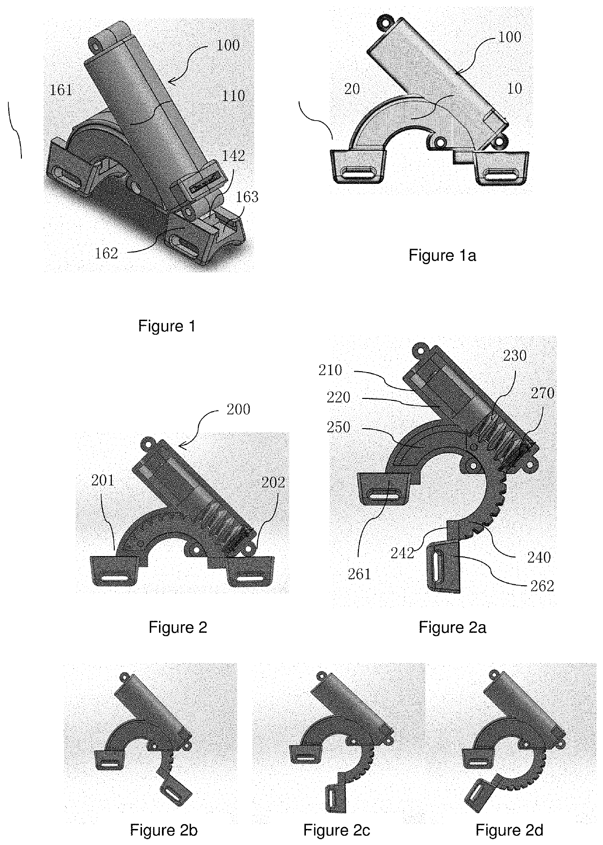
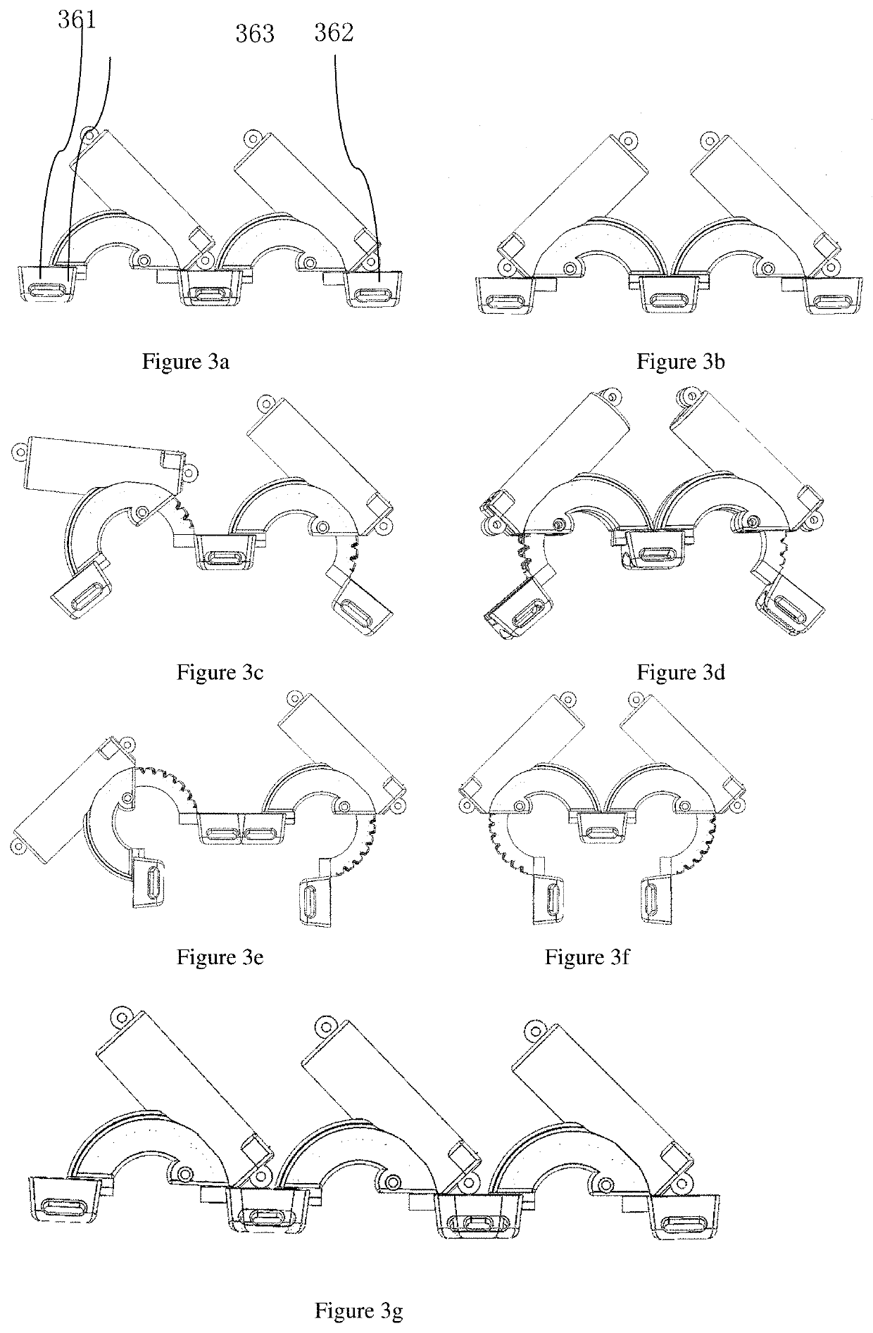
[0024]According to the present disclosure, it provides a body joint manipulator devised to rotate body parts according to the joint axial, and allows the manipulation of body parts in which the body joints are inaccessible. The manipulator consists of an integration of an actuator, a transmission gear, a partial gear wheel as a moving arm and a housing preferably having an arc channel to guide the movement of the geared arm. The geared arm and / or arc channel have connectors attached to the body parts and / or connect to each other. The manipulator can be configured as a single joint manipulator or it could be cascaded for multiple joints manipulation or composite movement manipulation of a single joint.

[0025]In some embodiments, the technical solution of t...


PUM


Abstract

A driving assembly for moving a first body part relative to a second body part comprising at least one manipulator unit for body part including a housing for accommodating at least partly of an actuator, a torque/force transmission gear, a partial gear wheel operatively connected with each other and a first connector arranged at a first/tail end of the manipulator unit for coupling with the first body part and a second connector movably arranged at a second/head end of the manipulator unit for coupling with the second body part and driven by the partial gear wheel actuated by the actuator via the torque transmission gear for coupling and moving with the second body part, and preferably an arc channel or rail for guiding back and forth movement of the partial gear wheel.

Description

TECHNICAL FIELD[0001]The present disclosure relates to a driving assembly, and more particularly to a driving assembly for moving or rotating, or assisting or resisting movement of, a first body part relative to a second body part, whereby enabling flexion, extension, pronation, supination, rotation, abduction, and adduction of the first body part relative to the second body part.BACKGROUND ART[0002]Existing technologies for manipulating body parts are usually configured for: positioning the motors / actuators directly on the joint rotation axial; or positioning a mechanical joint directly on the joint rotation axial and have the extension to be manipulated by actuators at a remote / distance site. Both designs require the body joint to be covered by motors and / or mechanical joints on one and / or both sides. Such an over-the-joint design requires the body part to be fitted in between the mechanical parts, and because of different limb circumferences, different sizes are needed. Sometimes...

Claims


Application Information

Patent Timeline
Patent Type & Authority Applications(United States)
IPC IPC(8): A61F2/58A61F2/72A61F5/01
CPCA61F2/586A61F2002/6836A61F5/013A61F2/72B25J9/08E05B47/06B25J9/0006A61H2201/5097A61H1/0237A61H2205/06A61H1/0285A61H2205/065A61H2205/067A61H2201/1207A61H2230/605A61H2205/086A61H2201/5069A61H2205/102A61H2205/088A61H1/02A61H2201/5061A61H2201/5058A61H2201/1238A61F2002/587A61F2002/704A61F2005/0155A61H2201/12
Inventor HO, SZE KIT
Owner HO SZE KIT
Why Eureka
Try Eureka