
Rifle bipod

a rifle and pinion technology, applied in the field of rifle pinions, can solve the problems of reducing the accuracy of the firearm supported thereon, bulky, inconvenient and difficult to use, and most shooters are not able to hold a firearm consistently in a set position without wavering, etc., to achieve the effect of convenient accurate and precise aiming

Active Publication Date: 2021-03-04
MCEWIN DESIGN PTY LTD
View PDF0 Cites 5 Cited by
  • Summary
  • Abstract
  • Description
  • Claims
  • Application Information

AI Technical Summary

Benefits of technology

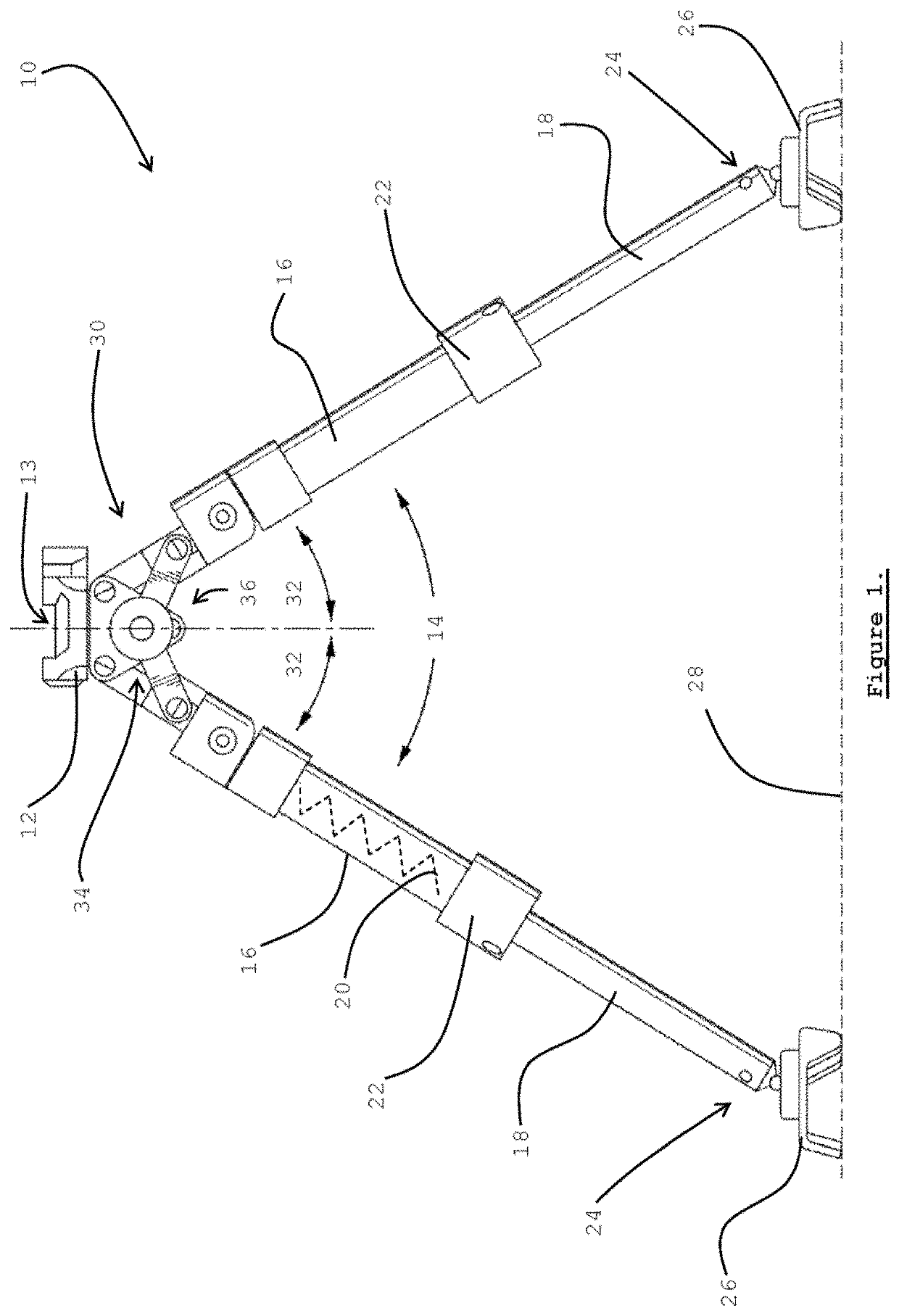
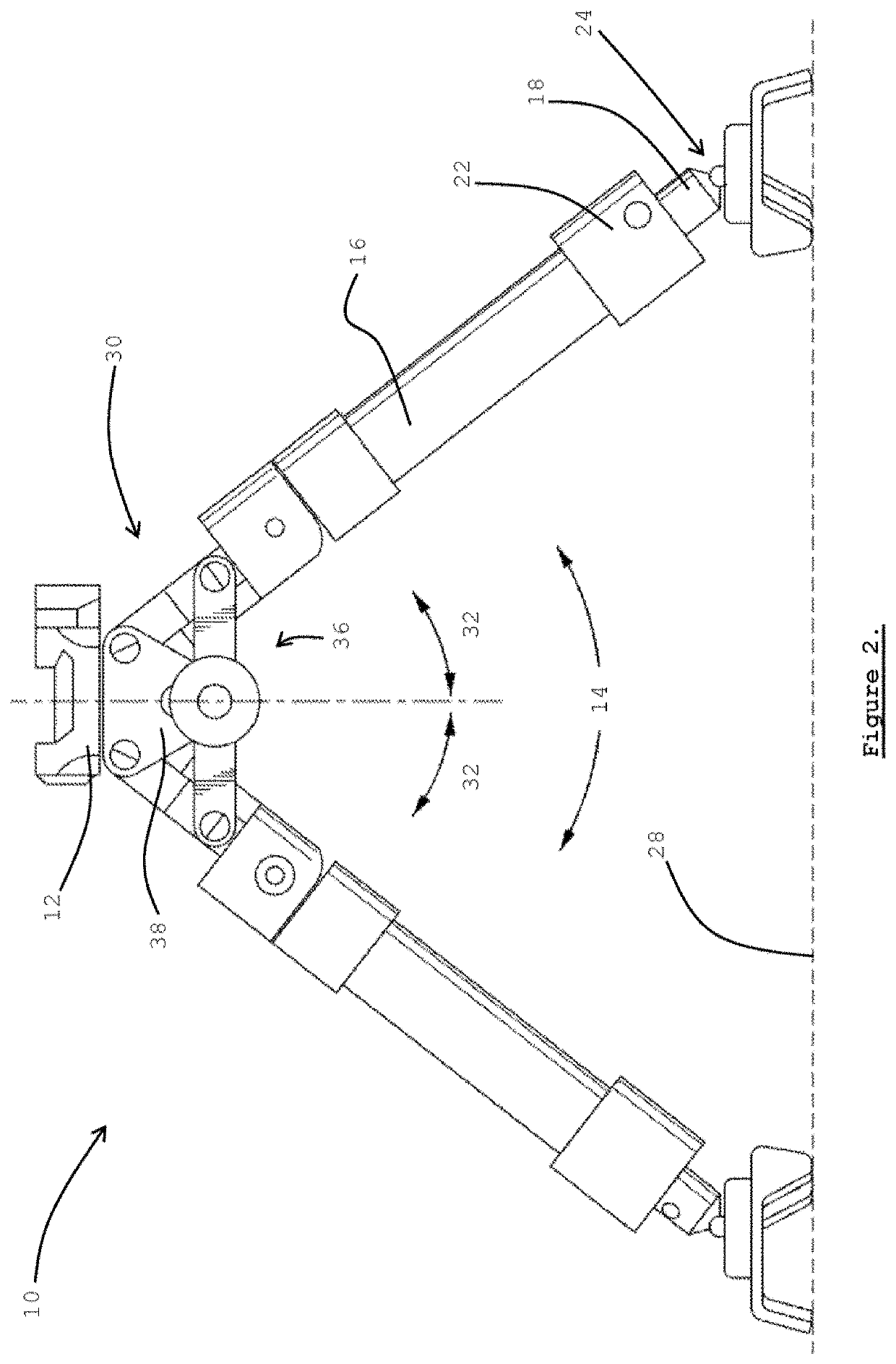
The patent text describes a stabilizing arrangement for a rifle. The arrangement includes a triangular member with a hole at the top for mounting the gun. The triangular member is attached to a support on the surface, and two rotating links are connected to the gun. These links allow the triangular member to pivot and adjust its angle. The bottom link is connected to a guiding slot in the support, which helps guide the triangular member's movement. This arrangement makes it easier and more precise to aim the rifle.

Problems solved by technology

Most shooters are not able to hold a firearm consistently in a set position without wavering, especially after the onset of fatigue resulting from strain due to the size and weight of the firearm.
Early bipod and tripod supports were typically somewhat crude stands that generally were bulky, inconvenient and difficult to use and typically were not easily adjustable.
A problem with conventional bipods has been in allowing adjustability of the bipod to suit a shooter's preference, rather than the shooter having to compensate for shortcomings of the bipod.
A further shortcoming with conventional bipods is that various surfaces on which a bipod can be rested can affect the stability thereof, leading to reduced accuracy from a firearm supported thereon.

Method used


Image

  • Rifle bipod
  • Rifle bipod
  • Rifle bipod

Examples


Embodiment Construction

[0049]Further features of the present invention are more fully described in the following description of several non-limiting embodiments thereof. This description is included solely for the purposes of exemplifying the present invention to the skilled addressee. It should not be understood as a restriction on the broad summary, disclosure or description of the invention as set out above. In the figures, incorporated to illustrate features of the example embodiment or embodiments, like reference numerals are used to identify like parts throughout.

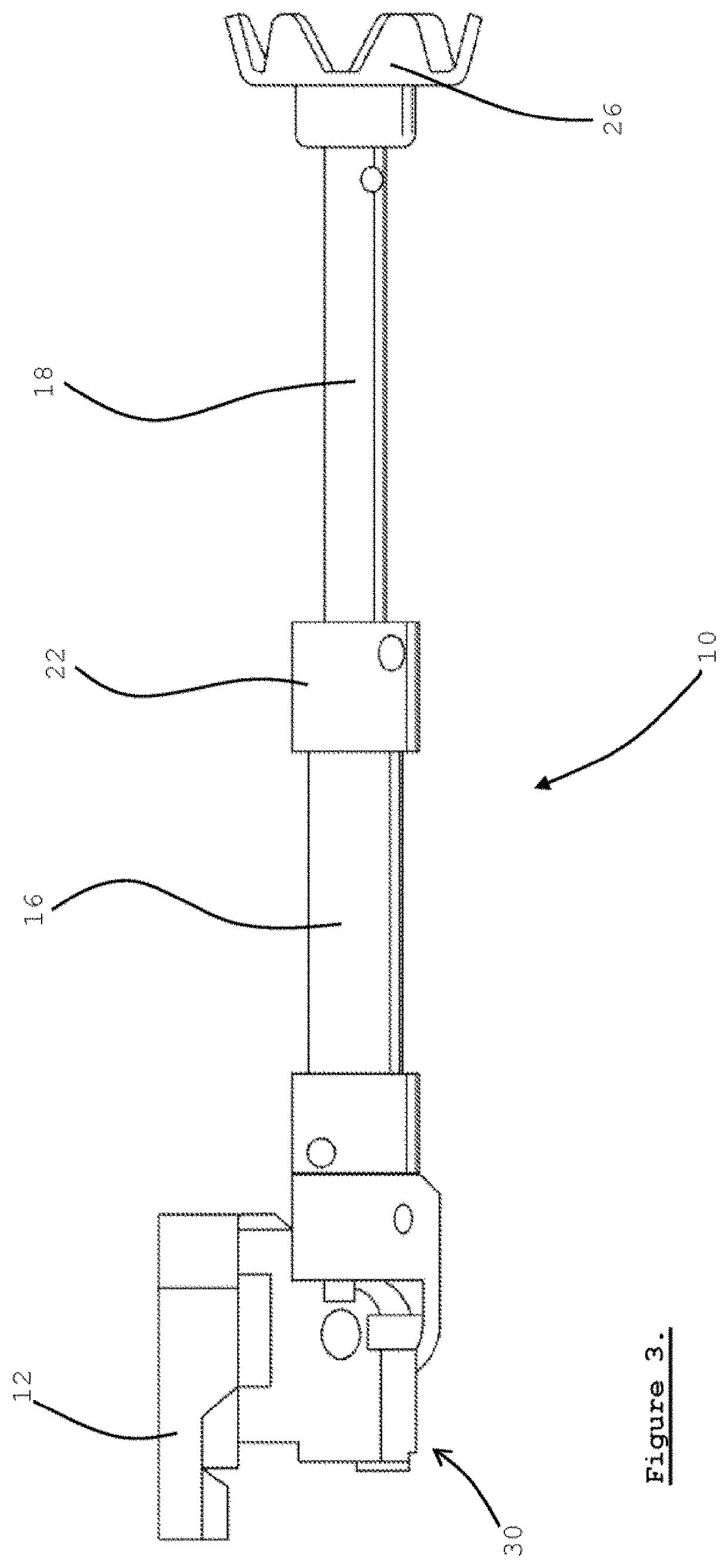
[0050]With reference now to the accompanying figures, there is shown one embodiment of a rifle bipod 10. The exemplified embodiment of the rifle bipod 10 broadly comprises a rifle support 12, two legs 14, and a stabilising arrangement 30. The bipod 10 is shown resting on a surface 28.

[0051]The rifle support 12 is typically configured for operatively receiving and supporting a portion of a rifle 8 thereon and / or thereby. In the present examp...


PUM


Abstract

A rifle bipod with a rifle support for operatively receiving and supporting a portion of a rifle, as well as two legs each having a tubular upper and lower portion and telescopically arranged with an urging element urging the portions and into an extended position is disclosed with a cam lock arrangement allowing infinite length adjustability between the telescoping upper and lower portions. Each leg has a foot attachment to releasably receive interchangeable feet whereby each leg is operatively able to engage a surface. Bipod also includes a stabilising arrangement pivotably attaching the legs to the rifle support at a commensurate off-vertical angle with a biasing element to operatively bias both legs towards each other. The stabilising arrangement includes a linkage to maintain the off-vertical angle commensurate as the legs pivot apart, wherein the rifle support is height adjustable via the telescoping legs and the linkage maintaining the off-vertical angle.

Description

TECHNICAL FIELD[0001]This invention relates to a rifle bipod and an associated method of supporting a rifle.BACKGROUND ART[0002]The following discussion of the background art is intended to facilitate an understanding of the present invention only. The discussion is not an acknowledgement or admission that any of the material referred to is or was part of the common general knowledge as at the priority date of the application.[0003]When shooting rifles and other firearms, especially in stressful tactical situations, it is important that the firearm be maintained in a steady, stable position to insure accuracy of aim. Most shooters are not able to hold a firearm consistently in a set position without wavering, especially after the onset of fatigue resulting from strain due to the size and weight of the firearm. Accordingly, peripheral support devices have been used in conjunction with firearms since the early creation of firearms as a means of stabilising a firearm to reduce vibratio...

Claims


Application Information

Patent Timeline
Patent Type & Authority Applications(United States)
IPC IPC(8): F41A23/10F41A27/30
CPCF41A23/10F41A27/30
Inventor FAVORY, COREY
Owner MCEWIN DESIGN PTY LTD
Learn More