Power supply apparatus and image forming apparatus

a technology of power supply apparatus and image forming apparatus, which is applied in the direction of electrographic process apparatus, instruments, optics, etc., can solve the problems of increasing the number of power supply boards, reducing cooling efficiency, and increasing the number of power supply boards. , to achieve the effect of increasing the number of types of electrical components of machines, increasing the power supply capacity, and increasing the ppm

Active Publication Date: 2020-12-31
KONICA MINOLTA INC
View PDF0 Cites 0 Cited by
  • Summary
  • Abstract
  • Description
  • Claims
  • Application Information

AI Technical Summary

Benefits of technology

The patent text describes the problem of machines having a rising internal temperature due to the increasing number of types of electrical components and power supply capacity, which can cause malfunctions and damage to power supply boards. The conventional configurations for air exhausting and heat insulation also decrease cooling efficiency and performance. The objective of the patent is to provide a power supply apparatus and an image forming apparatus that can prevent increase in internal temperature and malfunctions for power supply boards.

Problems solved by technology

Such a power supply apparatus generates heat by operating, and when overheating, declines in function and becomes unstable, and also causes problems in peripherals.
In addition, internal temperature of machines has been on a rising trend with increase in PPM because the size of machines cannot be increased much due to requests for downsizing.
In such a situation, conventional configurations for air exhausting and heat insulation cause power supply boards to have a temperature exceeding the upper limit of target temperature, and consequently cause malfunctions of machines and damage to the power supply boards.
However, in the case of the configuration disclosed in JP 2007-240657 A, increasing the number of power supply boards decreases cooling efficiency, and accordingly decreases cooling performance of power supply boards.
Further, as the number of power supply boards is increased, the number of air-blowing fans is increased, which increases noise level and costs.

Method used


Image

  • Power supply apparatus and image forming apparatus
  • Power supply apparatus and image forming apparatus
  • Power supply apparatus and image forming apparatus

Examples


Embodiment Construction

[0026]Hereinafter, one or more embodiments of the present invention are described in detail with reference to the drawings. However, the scope of the present invention is not limited to the embodiments or illustrated examples.

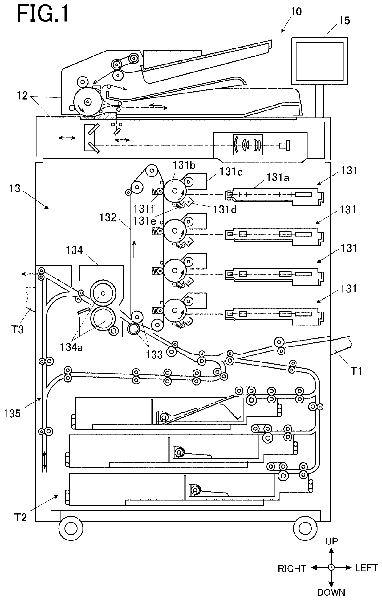
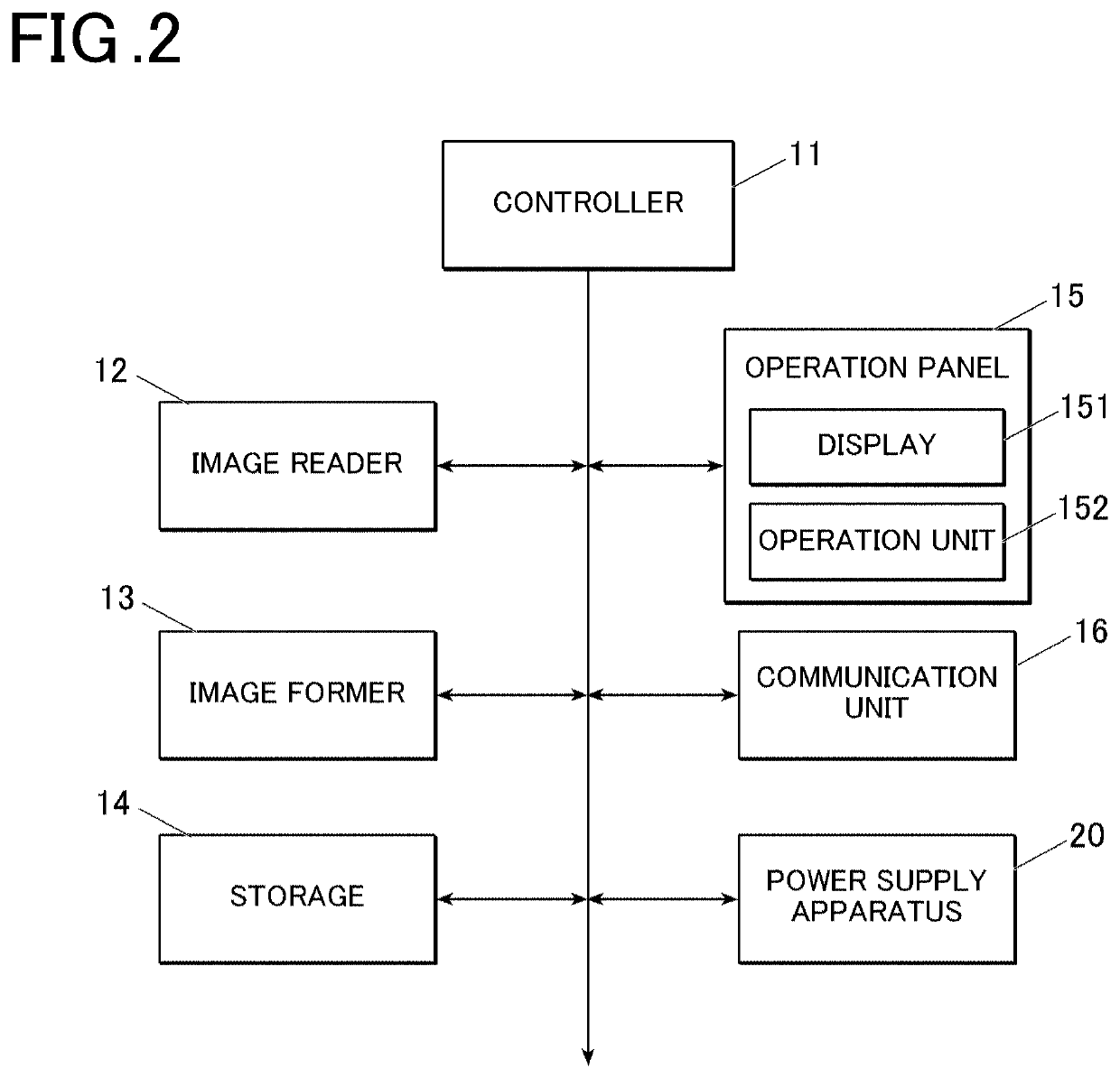
[0027]An image forming apparatus 10 according to an embodiment(s) includes, as shown in FIG. 1 and FIG. 2, a controller 11 (hardware processor), an image reader 12, an image former 13, a storage 14, an operation panel 15 (a display 151 and an operation unit 152), a communication unit 16 and a power supply apparatus 20.

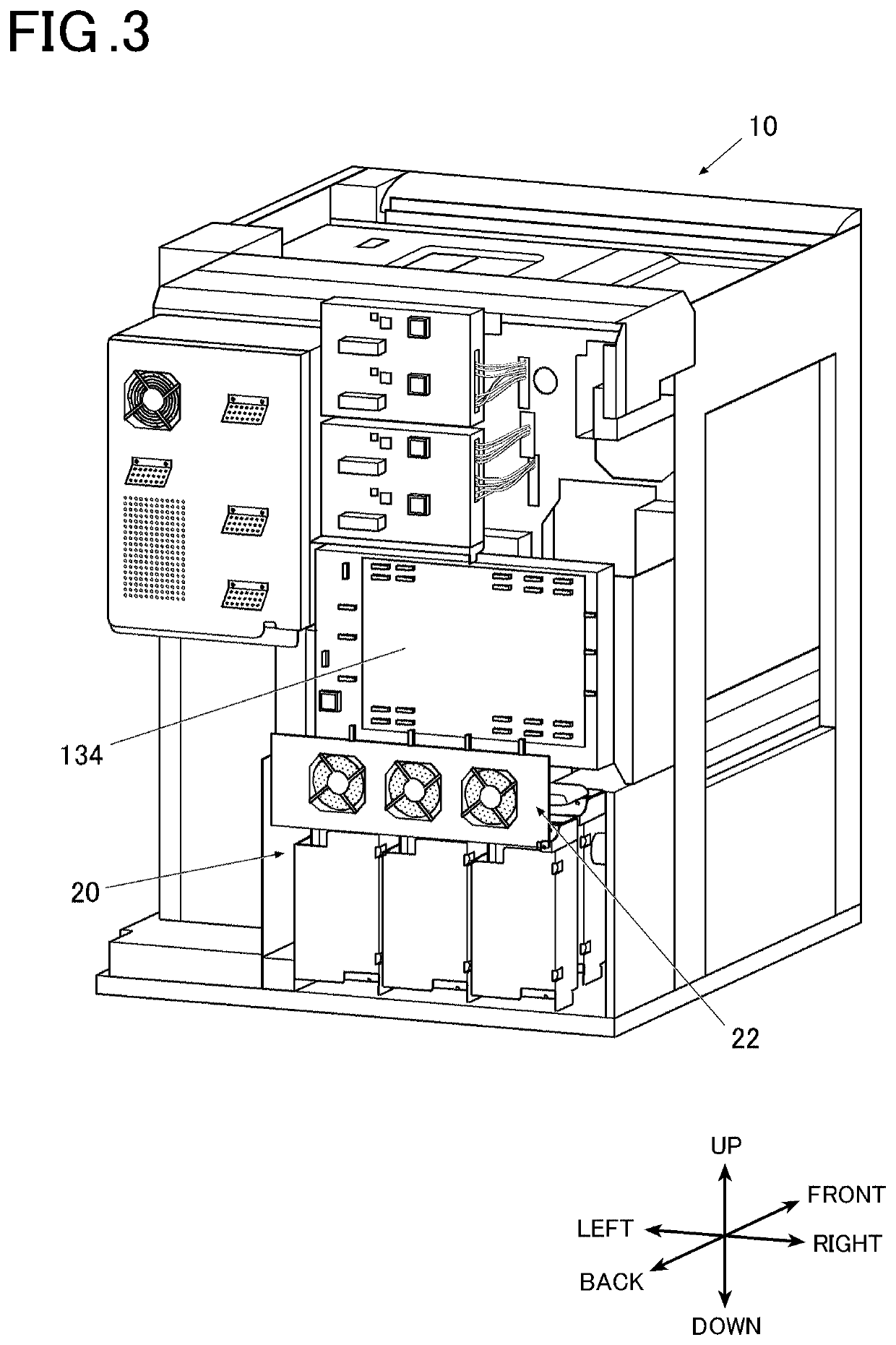
[0028]In the following description, an operational surface side of the image forming apparatus 10 is referred to as front (front side), and a plane on the deep side facing the front is referred to as back (back side). The depth direction from / to the front to / from the back is referred to as front-back direction, the horizontal direction orthogonal to the front-back direction is referred to as left-right direction, and a direction orthogonal to the ...


PUM


Abstract

A power supply apparatus includes a plurality of power supply boards and a cooler. The power supply boards supply power. The cooler cools the power supply boards. The power supply boards are disposed in rows in a front-back direction and stepwise so as to be disposed more upward as disposed more forward.

Description

CROSS-REFERENCE TO RELATED APPLICATIONS[0001]The present invention claims priority under 35 U.S.C. § 119 to Japanese Patent Application No. 2019-117975 filed Jun. 26, 2019, the entire content of which is incorporated herein by reference.BACKGROUNDTechnological Field[0002]The present disclosure relates to a power supply apparatus and an image forming apparatus.Description of the Related Art[0003]Conventionally, there has been known an electrophotographic image forming apparatus that forms an image on a sheet of paper by developing an electrostatic latent image formed on a photoreceptor with toner, thereby forming a toner image, transferring the formed toner image onto a sheet of paper, and heating and fixing the transferred toner image to the sheet.[0004]The abovementioned image forming apparatus includes a power supply apparatus that transforms power into low-voltage power for driving mechanical components relevant to image forming.[0005]Such a power supply apparatus generates heat ...

Claims


Application Information

Patent Timeline
Patent Type & Authority Applications(United States)
IPC IPC(8): G03G15/00G03G15/20G03G21/20
CPCG03G15/2017G03G21/206G03G15/5004G03G21/20G03G15/80G03G21/1619
Inventor KAWABATA, SHINICHIWATANABE, KANEHIRO
Owner KONICA MINOLTA INC
Why Eureka
Try Eureka