Printing apparatus
a printing apparatus and head portion technology, applied in printing, typewriters, power drive mechanisms, etc., can solve the problems of greatly affecting printing quality, and achieve the effects of reducing the influence of airflow on the droplets ejected after the reverse motion of the head portion, and reducing the influence of airflow
- Summary
- Abstract
- Description
- Claims
- Application Information
AI Technical Summary
Benefits of technology
Problems solved by technology
Method used
Image

Examples
first embodiment
A. First Embodiment
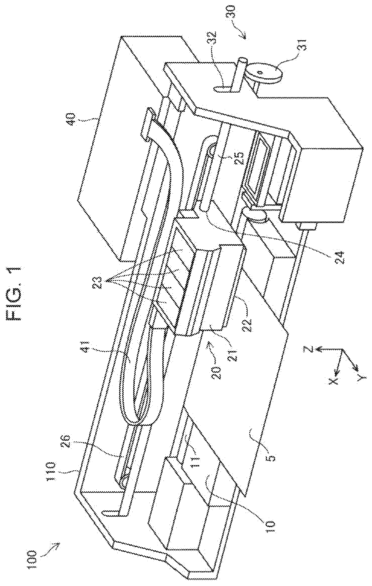
[0032]FIG. 1 is a perspective view illustrating a schematic configuration of a printing apparatus 100 according to a first embodiment. The printing apparatus 100 is configured as a serial ink jet printer that performs printing by ejecting inks onto a printing medium 5. The printing apparatus 100 includes a platen 10, a head portion 20, an interval adjusting mechanism 30, and a controller 40. The printing apparatus 100 can perform printing on various media such as a printing paper, a cloth, a cardboard, and an acrylic board, as the printing medium 5.
[0033]An X direction, a Y direction, and a Z direction which are perpendicular to each other are illustrated in FIG. 1. These directions are illustrated in figures after FIG. 1 as needed. In the present embodiment, a +X direction is a forward direction in a direction in which the head portion 20 reciprocates, and a −X direction is a rearward direction in the direction in which the head portion 20 reciprocates. A +Y dire...
second embodiment
B. Second Embodiment
[0047]In the above-described first embodiment, the controller 40 controls the interval adjusting mechanism 30 depending on the printing mode designated by the user, to adjust the platen gap. In contrast, in the second embodiment, the controller 40 adjusts the platen gap according to the thickness of the printing medium 5 without designating the printing mode by the user.
[0048]FIG. 6 is a perspective view illustrating a schematic configuration of a printing apparatus 100a according to the second embodiment. The printing apparatus 100a according to the second embodiment is different from the printing apparatus 100 illustrated in FIG. 1 according to the first embodiment in that the former includes a distance measuring unit 50 for measuring the distance between the head portion 20 and the printing medium 5, and the other configurations are the same. Hereinafter, the same configurations in the printing apparatus 100a and the printing apparatus 100 will be described us...
third embodiment
C. Third Embodiment
[0053]In the above-described first embodiment, the platen gap and the movement stop time are set according to the printing mode designated by the user. In contrast, in the third embodiment, the movement stop time is set based on the paper gap measured using the distance measuring unit 50. A configuration of a printing apparatus according to the third embodiment is the same as the printing apparatus 100a (FIG. 6) according to the second embodiment.
[0054]FIG. 8 is a diagram illustrating control contents of the controller 40 according to the present embodiment. In the present embodiment, prior to the printing, the controller 40 measures paper gaps D (D1 and D2) using the distance measuring unit 50 as described above. Thus, the controller 40 controls the movement of the head portion 20 during the printing such that the movement stop time ti of the head portion 20 when the movement direction of the head portion 20 is reversed becomes longer as the paper gap D becomes l...
PUM
 Abstract
Description
Claims
Application Information
 - Generate Ideas
- Intellectual Property
- Life Sciences
- Materials
- Tech Scout
- Unparalleled Data Quality
- Higher Quality Content
- 60% Fewer Hallucinations
Browse by: Latest US Patents, China's latest patents, Technical Efficacy Thesaurus, Application Domain, Technology Topic, Popular Technical Reports.
© 2025 PatSnap. All rights reserved.Legal|Privacy policy|Modern Slavery Act Transparency Statement|Sitemap|About US| Contact US: help@patsnap.com