
Expandable splice for a solar power system

a solar power system and support structure technology, applied in the direction of photovoltaic supports, heat collector mountings/supports, light and heating apparatus, etc., can solve the problems of arrays being less efficient, bending, or deflection along a length of the support structure, and the support does not necessarily distribute the load or strain sufficiently along a length of the torque tube to prevent distortion or bending, so as to prevent warping or bowing, the effect of easy insertion

Active Publication Date: 2020-12-24
NEXTRACKER LLC
View PDF0 Cites 4 Cited by
  • Summary
  • Abstract
  • Description
  • Claims
  • Application Information

AI Technical Summary

Benefits of technology

The present disclosure describes an expandable splice that can reinforce a support structure, such as a torque tube, of a solar power system. The expandable splice can transition between a narrow and expanded configuration to provide additional strength to the support structure and prevent warping or bowing. The expandable splice includes at least one beveled corner panel that allows it to more easily fit within a channel of the support structure. In the expanded configuration, the beveled corner secures the side panel against the inner surface of the support structure thereby distributing any future load or strain along a length of the support structure.

Problems solved by technology

The forces on the structure due to wind can be intensified or concentrated at the connections, joints, and fasteners in the rail system and horizontal support structure potentially resulting in deflection, bending, or failure along a length of the support structure.
Any such deflection or bending can cause the array to be less efficient due to lack of total alignment and / or the inability of the torque tube to properly pivot due to the distortion or bending.
Additional support may be applied to the array of solar modules or the specific point of attachment, however such support does not necessarily distribute the load or strain sufficiently along a length of the torque tube to prevent distortion or bending.

Method used


Image

  • Expandable splice for a solar power system
  • Expandable splice for a solar power system
  • Expandable splice for a solar power system

Examples


Embodiment Construction

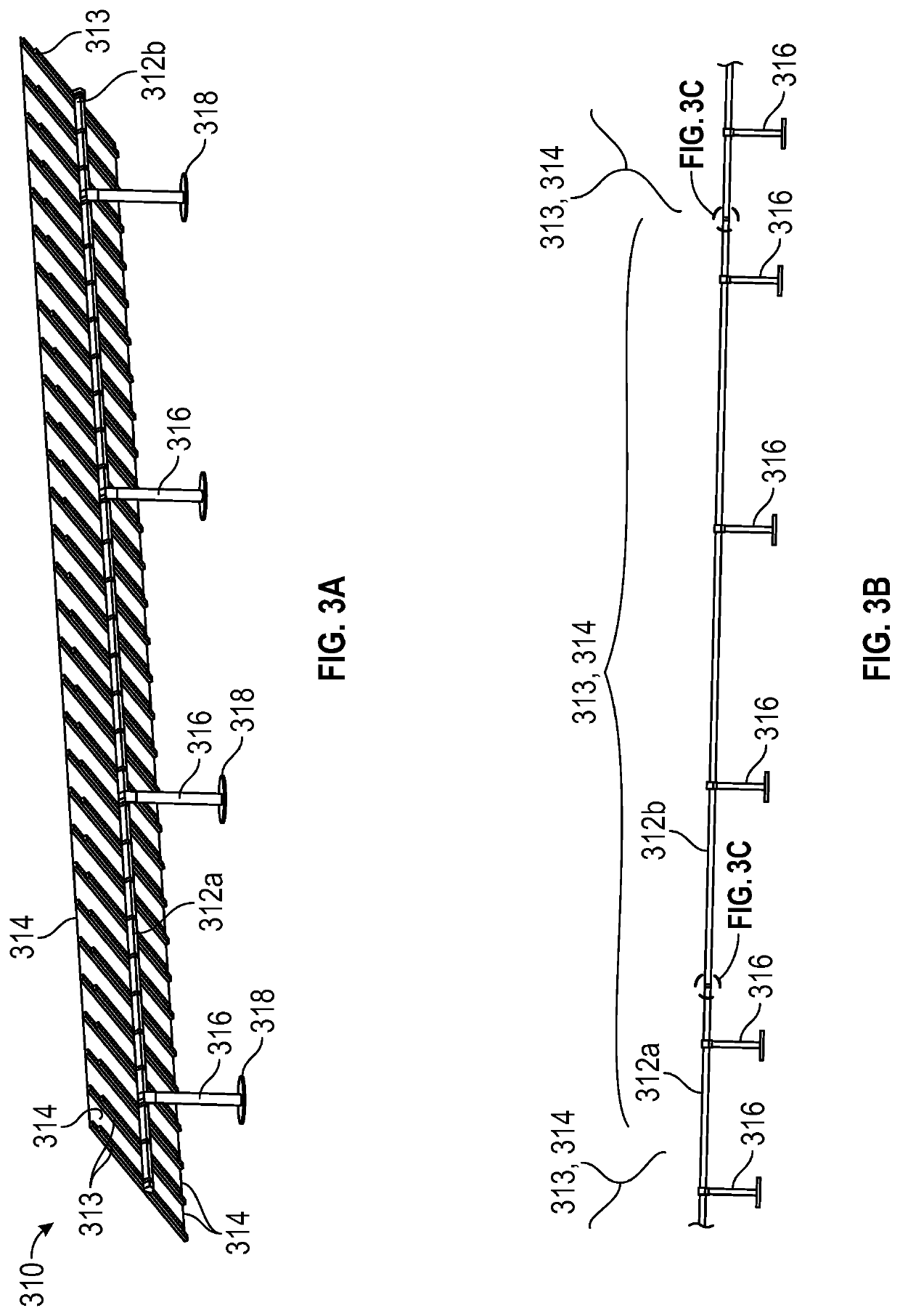
[0026]The present disclosure describes an expandable splice configured to reinforce a support structure, such as a torque tube, of a solar power system. The solar power system may be any type of solar power system, such as a roof-top solar power system, or a solar tracker system, and the like. In particular embodiments, the solar power system is a solar tracker system including at least one ground-based support structure, such as a pile, and an array of solar modules mounted and secured to the ground-based support structure and in particular a rail or torque tube extending generally perpendicular from the support structure (see FIGS. 3A-3C).

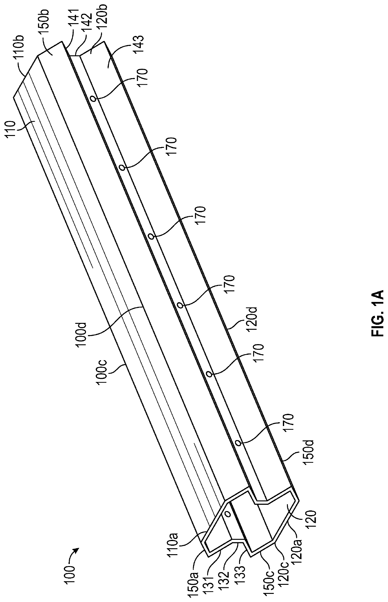
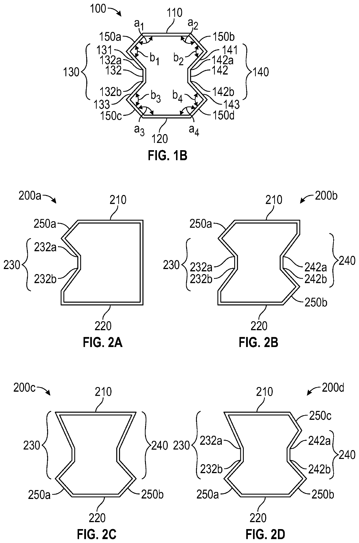
[0027]The expandable splice is configured to transition between a narrow configuration (see FIGS. 1A-2D) and an expanded configuration (see FIG. 4B). In some embodiments, the expandable splice includes at least one beveled corner panel and at least one side panel including two or more transition points or bend points.

[0028]Turning now to FIGS. 1A...


PUM


Abstract

The present disclosure describes an expandable splice configured for reinforcing a tube of a solar owner system, the splice including a top panel, a bottom panel, a first side panel, a second side panel, and at least one beveled corner panel, wherein the first and second side panels are connected to the top and bottom panels either directly or by the at least one beveled corner panel to form a channel therebetween.

Description

BACKGROUND1. Technical Field[0001]The present disclosure relates to an expandable splice for a support structure of a solar power system. More particularly, the present disclosure relates to an expandable splice including at least one beveled corner panel and configured to transition between a narrow configuration and an expanded configuration to reinforce the support structure of the solar power system.2. Discussion of Related Art[0002]Solar power has long been viewed as an important alternative energy source. To this end, substantial efforts and investments have been made to develop and improve upon solar energy collection technology. Of particular interest are residential-, industrial- and commercial-type applications in which relatively significant amounts of solar energy can be collected and utilized in supplementing or satisfying power needs. One way of implementing solar energy collection technology is by assembling an array of multiple solar modules.[0003]Solar modules can e...

Claims


Application Information

Patent Timeline
Patent Type & Authority Applications(United States)
IPC IPC(8): H02S20/32F24S25/60H01L31/042H02S20/10H02S30/10F24S25/20
CPCH01L31/042F24S2025/6009F24S25/20H02S20/10F24S25/60F24S2025/014H02S30/10H02S20/32F24S2080/09F24S30/425F24S25/12F24S25/65F24S2025/6006Y02E10/47Y02E10/50
Inventor KRESSE, DAVIDHELLER, SAM
Owner NEXTRACKER LLC
Learn More