Spine Extension Roller

a roller and spine technology, applied in the field of spine extension rollers, can solve the problems that one cannot effectively counterbalance the spinal flexion, and achieve the effects of increasing spinal extension, spinal extension, and positive manipulation of the spine's facet joints

Pending Publication Date: 2020-12-24
DRATH THOMAS WALTER +1
View PDF7 Cites 2 Cited by
  • Summary
  • Abstract
  • Description
  • Claims
  • Application Information

AI Technical Summary

Benefits of technology

[0004]This invention comprises two key elements: (1) the roller and (2) the grab bars. When combined as described herein, the invention provides its user with a more effective method of positively manipulating the spine's facet joints and achieving spinal extension. In addition, this invention allows a user to mobilize the entire length of the spine, from the base of the occipital to the sacrum.
[0005]The spatial relationship between the roller and the grab bars allow a user to dynamically increase spinal extension as shown in FIGS. 2-3. By holding on the grab bars while dropping the hips, a user can self-achieve greater levels of facet manipulation, thereby allowing a user more effective results in a shorter period of time. Without grab bars, one simply cannot effectively counterbalance the spinal flexion that is invariably imposed on the human body functioning in a primarily sedentary culture.
[0006]The roller / grab bar combination enables a user to re-establish more favorable spinal facet extension in (a) a horizontal closed kinetic chain environment and (b) a non-compressive spinal loading environment (see FIGS. 2-3). This environment provides a user with more control as the user attempts greater range of motion in the facet joints. Typical standing and back-bending environments common in yoga and other practices are performed in open kinetic chain and under spinal load, and with inherently less user control.

Problems solved by technology

Without grab bars, one simply cannot effectively counterbalance the spinal flexion that is invariably imposed on the human body functioning in a primarily sedentary culture.

Method used


Image

  • Spine Extension Roller
  • Spine Extension Roller
  • Spine Extension Roller

Examples


Embodiment Construction

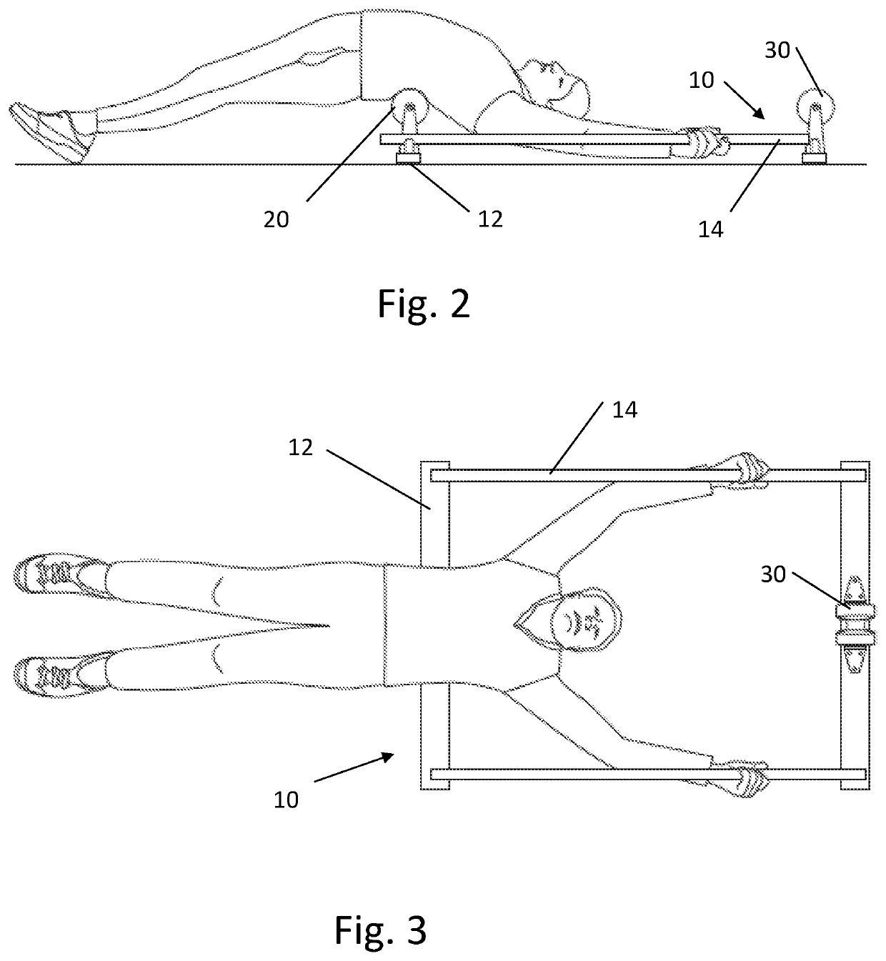
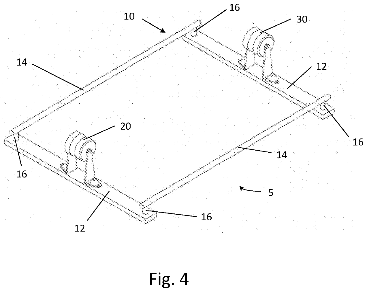
[0032]The invention is embodied in an apparatus for extending the human back. As shown in FIGS. 2-9, the preferred apparatus has a frame 10, comprising transverse members 12 and longitudinal members 14. A roller 20 is rigidly supported from below by the transverse member 12. The space above the roller 20 and frame 10 is open so that a user can lie face up on the roller and grab the longitudinal members 14 with each hand to extend the back over the top of the roller as illustrated in FIG. 2-3. The user then lowers his hips to extend the spine as much as desired. The user can roll the spine, vertebrae by vertebrae, from the base of the occipital to the sacrum.

[0033]The preferred frame 10 is constructed from steel members bolted together, although welding or most any connection known in the art would suffice. The transverse member 12 is preferably a rectangular tube. The longitudinal members 14 are preferably circular tubes connected to the top sides of transverse members 12 at joints ...


PUM


Abstract

The invention is embodied in an apparatus for extending the human back. The preferred apparatus has a frame of transverse and longitudinal members, and a roller 20 rigidly supported from below by a transverse member. The space above the roller and frame is open so that a user can lie face up on the roller and grab the longitudinal members with each hand to extend the back over the top of the roller. The user then lowers his hips to extend the spine as much as desired. The user can roll the spine, vertebrae by vertebrae, from the base of the occipital to the sacrum.

Description

FIELD OF THE INVENTION[0001]The present invention relates to rolling and extending the spine.BACKGROUND[0002]Foam rolling is a common technique and its benefits are well known. When foam rolling the back, a user will lie face up on a cylindrically-shaped foam roller with the roller oriented to roll lengthwise along the spine. The user may use the feet to assist moving the spine lengthwise over the foam roller. (See, e.g., FIG. 1.) While the benefits of foam rolling the back in this way are tangible, they are limited because a user's weight is distributed along the length of the roller. Once the user's body adjusts to the user's weight on the roller the benefits, while still tangible, diminish over time.[0003]What is needed is an improved spine roller that can load the facet joints more directly and to a greater degree in order to provide additional benefits to a user beyond what the user could do with a foam roller alone.SUMMARY OF THE INVENTION[0004]This invention comprises two key...

Claims


Application Information

Patent Timeline
Patent Type & Authority Applications(United States)
IPC IPC(8): A61H15/00
CPCA61H2205/081A61H2201/0119A61H2201/1253A61H2201/1635A61H2015/0014A61H15/00A61H2201/1623A61H2203/0456A61H2201/0161A61H2201/1284A61H15/02A61H1/0292A61H2201/0192
Inventor DRATH, THOMAS WALTERDRATH, DANIEL ALBERT
Owner DRATH THOMAS WALTER
Why Eureka
Try Eureka