
Methods for securing a transcatheter valve to a bioprosthetic cardiac structure

a bioprosthetic valve and transcatheter valve technology, applied in the field of transcatheter valve implantation in a bioprosthetic valve or a native valve, can solve the problems of insufficient expansion of the transcatheter valve inside the implanted tissue valve, the size of the transcatheter valve is too small to be secured into some larger bioprosthetic valve sizes, and the patient's outlive the life of the valv

Active Publication Date: 2020-11-12
EDWARDS LIFESCIENCES CORP
View PDF5 Cites 2 Cited by
  • Summary
  • Abstract
  • Description
  • Claims
  • Application Information

AI Technical Summary

Benefits of technology

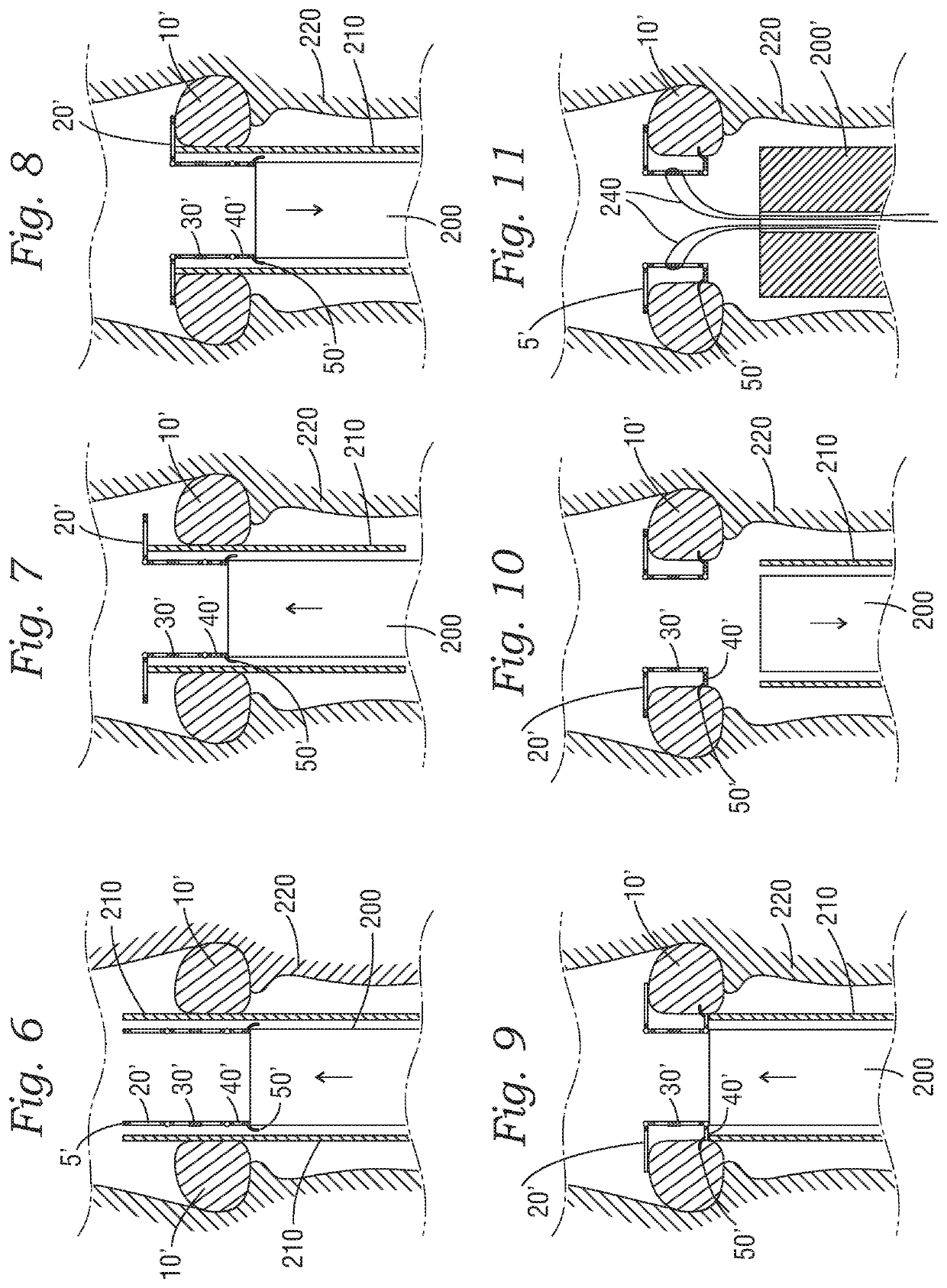
[0011]Another aspect is a method of providing a securing surface for a transcatheter valve within a bioprosthetic structure. The structure has a central flow axis with an upstream direction and a downstream direction, the downstream direction corresponding to the direction of blood flow from an upstream portion of the bioprosthetic structure through flaps in a downstream portion of the structure when a spacer is implanted. The method may include providing a collapsible spacer for a bioprosthetic structure, collapsing the spacer to a reduced diameter, coupling the spacer to a distal end portion of an elongate catheter, advancing the elongate catheter through a patient's vasculature and delivering the spacer into position relative to the bioprosthetic structure, and expanding the spacer to provide an engagement surface for a transcatheter heart valve.

Problems solved by technology

Although the durability of bioprosthetic valves has improved, some patients outlive the life of the valve, for example, when structural deterioration causes the valve to fail.
Such transcatheter valves are too small to be secured into some larger bioprosthetic valve sizes, however.
A challenge with valve-in-valve replacements in the larger valves is that the transcatheter valve may not be large enough to sufficiently expand inside the implanted tissue valve to stay in place and to be competent.
If the transcatheter valve is expanded too much, the leaflets of the valve may not properly come together or coapt for the valve to function properly.

Method used


Image

  • Methods for securing a transcatheter valve to a bioprosthetic cardiac structure
  • Methods for securing a transcatheter valve to a bioprosthetic cardiac structure
  • Methods for securing a transcatheter valve to a bioprosthetic cardiac structure

Examples


Embodiment Construction

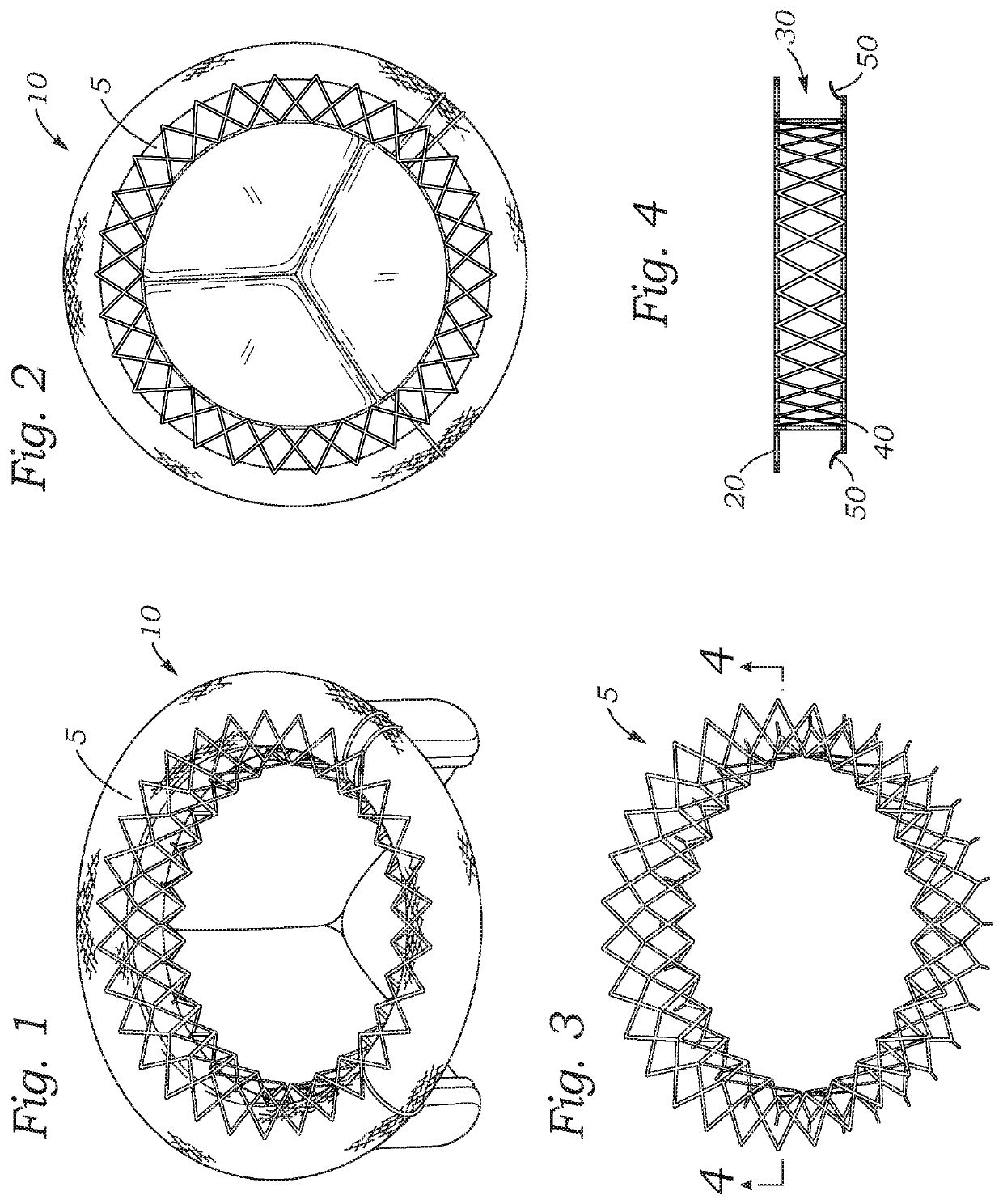
[0038]FIG. 1 illustrates one embodiment of a spacer ring 5 deployed in a surgical mitral or tricuspid prosthetic valve 10, for example, a Carpentier-Edwards PERIMOUNT Magna Mitral Ease® mitral heart valve (Model 7300TFX, Edwards Lifesciences, Irvine, Calif.). The spacer ring 5 is provided to narrow or reduce the space within an implanted bioprosthetic mitral, tricuspid, pulmonic, or aortic valve 10 into which the transcatheter valve is to be implanted, for example, a surgically implantable bioprosthetic valve. As discussed above, the spacer ring 5 is useful in situations in which an interior space or lumen of a previously implanted prosthetic valve is too large for direct implantation of a largest available transcatheter valve therein. FIG. 2 is a top view of the same spacer ring 5 in place on the surgical mitral or tricuspid valve 10. FIG. 3 is a perspective view of the spacer ring itself, and FIG. 4 is a cross-section of the spacer ring of FIG. 3.

[0039]Considering FIG. 4, the spac...


PUM


Abstract

A spacer for creating a docking station for a transcatheter heart valve is provided. The spacer changes an effective diameter and / or a shape of an implanted bioprosthetic structure such as a bioprosthetic heart valve or annuloplasty ring, providing a supporting structure into which the transcatheter valve expands without over expanding. The spacer may be deployed through an interventional technique either through transseptal access, transfemoral access, or transapical access and is typically deployed at least in part on an inflow portion of the implanted bioprosthetic structure.

Description

CROSS REFERENCE TO RELATED APPLICATIONS[0001]This application is a continuation of U.S. patent application Ser. No. 15 / 494,239, filed Apr. 21, 2017, which is a continuation of International Patent Application No. PCT / US2016 / 050254, filed Sep. 2, 2016, which claims the benefit of U.S. Patent Application No. 62 / 213,559, filed Sep. 2, 2015, the entire disclosures of which are incorporated by reference herein.TECHNICAL FIELD[0002]The present disclosure relates to transcatheter valve implantation in a bioprosthetic valve or a native valve that has been repaired with an annuloplasty ring and, in particular, an apparatus and method to assist in securing the transcatheter valve in the bioprosthetic valve or to the annuloplasty ring.BACKGROUND[0003]Valve-in-valve transcatheter valve implantation is increasingly used when bioprosthetic heart valves fail. Bioprosthetic valves are used more often than mechanical valves, and increasingly, in younger patients. Although the durability of bioprosth...

Claims


Application Information

Patent Timeline
Patent Type & Authority Applications(United States)
IPC IPC(8): A61F2/24
CPCA61F2230/0054A61F2250/006A61F2220/0025A61F2/2412A61F2210/0014A61F2250/0096A61F2250/0063A61F2/2448A61F2/2409A61F2/2433A61F2/2418
Inventor CAMPBELL, LOUIS A.
Owner EDWARDS LIFESCIENCES CORP
Learn More