
Correlating user interface design types to user groups

a user interface and design type technology, applied in the field of user interface technology, can solve the problems of many entities not having access to coding or design expertise, and achieve the effect of improving user experience and coding skills

Active Publication Date: 2020-10-29
SALESFORCE COM INC
View PDF0 Cites 14 Cited by
  • Summary
  • Abstract
  • Description
  • Claims
  • Application Information

AI Technical Summary

Benefits of technology

The patent describes a system for automatically generating user interface designs. This system can use various techniques to create customized user interfaces that meet the needs of different entities. The technical effects of this system include the ability to automatically generate user interface designs that are customized to the needs of different entities, without requiring coding or design expertise. The system can also use machine learning to improve the user interface design process. Overall, the system provides a more efficient and effective way to create customized user interfaces.

Problems solved by technology

Many entities do not have access, however, to coding or design expertise needed to generate an effective user experience.

Method used


Image

  • Correlating user interface design types to user groups
  • Correlating user interface design types to user groups
  • Correlating user interface design types to user groups

Examples


example customized

User Interfaces

[0177]FIG. 19 is a block diagram illustrating two example customized user interfaces, according to some embodiments. In the illustrated embodiment, user interfaces 1912A and 1912B display different subsets, with different formatting, of a set of information for three pairs of shoes.

[0178]In the illustrated embodiment, user interface 1912A displays, for each shoe, a subset of that shoe's set of information that includes price, image, and description. Similarly, user interface 1912B displays, for each shoe, a second subset of that shoe's set of information that includes image and star rating. Note that the sets of information for each shoe may include price, image, description (e.g., men's hiking boot, men's work boot, and men's waterproof boot), and star rating, where user interfaces 1912A and 1912B display different subsets of the set of information for each shoe.

[0179]In the illustrated example, user interfaces 1912 vary in both content and formatting of the content....

example method

for User Interface Customization

[0182]FIG. 20 is a flow diagram illustrating an example method for generating different user interfaces using different formatting, according to some embodiments. The method shown in FIG. 20 may be used in conjunction with any of the computer circuitry, systems, devices, elements, or components disclosed herein, among other devices. In various embodiments, some of the method elements shown may be performed concurrently, in a different order than shown, or may be omitted. Additional method elements may also be performed as desired.

[0183]At 2010, in the illustrated embodiment, a computing system maintains, using one or more storage elements, a set of information that includes multiple types of information.

[0184]At 2020 the computing system accesses, based on a first request by a first user, the set of information.

[0185]At 2030 the computing system determines a first subset of the set of information based on a set of attributes of the first user. In some...


PUM


Abstract

Techniques are disclosed relating to providing customized user interfaces to different groups of users. A computing system may determine a plurality of different design types for a user interface and cause display of user interfaces that exhibit the different design types to different users. Based on user interactions with the user interfaces, the system may generate one or more metrics. The system may and may determine attribute values for attributes of users who interact with the user interface. The system may perform one or more correlation procedures to correlate the attribute values with one or more of the metrics. In disclosed embodiments, the computing system generates groups of users based on the correlation. The computing system may assign at least one of the design types to at least one of the groups of users based on the correlation.

Description

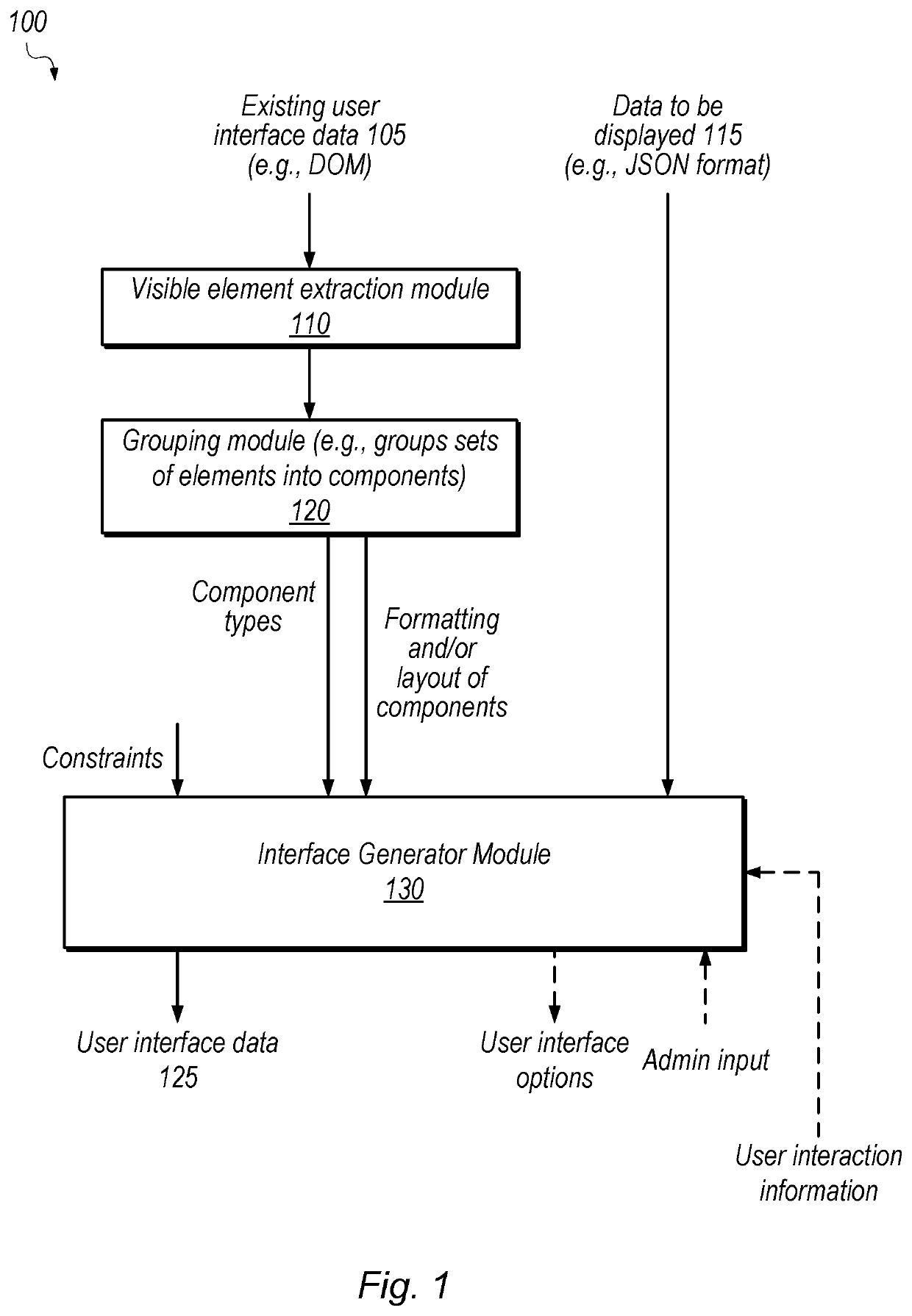
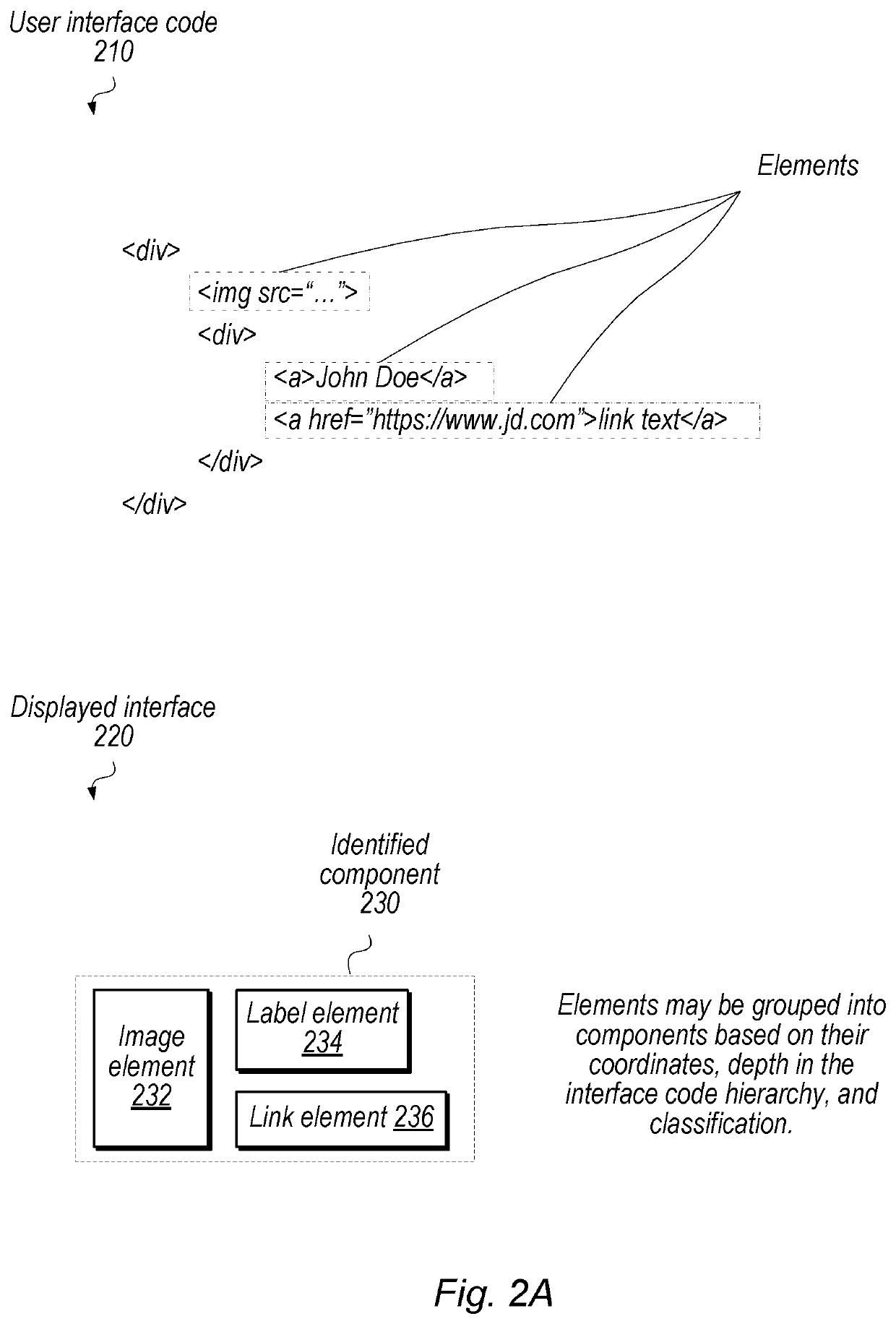
BACKGROUNDTechnical Field[0001]Embodiments described herein relate to user interface technology and, in particular, to techniques for automatically generating customized user interfaces.Description of the Related Art[0002]User interfaces are often generated by multiple skilled designers, e.g., to combine quality coding techniques with graphical design to achieve desired functionality while pleasing the eye, achieving branding goals, or promoting desired user behaviors. Many entities may desire customized interfaces rather than using generic templates. Many entities do not have access, however, to coding or design expertise needed to generate an effective user experience.BRIEF DESCRIPTION OF THE DRAWINGS[0003]FIG. 1 is a block diagram illustrating an example system for automatically generating user interface data, according to some embodiments.[0004]FIG. 2A is a diagram illustrating example user interface code and a resultant display of an identified component, according to some embo...

Claims


Application Information

Patent Timeline
IPC IPC(8): G06F9/451G06F8/20G06N20/00G06F3/0481
CPCG06F3/0481G06N20/00G06F8/20G06F9/451G06F11/3438G06F11/3466G06Q10/101G06Q30/0241G06F16/9035
Inventor ROHDE, SÖNKELONSDORF, BRIAN J.SCHOPPE, OWEN WINNE
Owner SALESFORCE COM INC
Learn More