Aeration amount control system and aeration amount control method
a technology of aeration amount and control system, which is applied in the direction of sustainable biological treatment, biological water/sewage treatment, membranes, etc., can solve the problems of reducing the efficiency of filtering, the energy cost of aeration by the aeration device is estimated to reach approximately half the whole operating cost of the aeration amount control system, etc., to achieve energy cost reduction, energy cost reduction, and energy cost reduction
- Summary
- Abstract
- Description
- Claims
- Application Information
AI Technical Summary
Benefits of technology
Problems solved by technology
Method used
Image

Examples
embodiment 1
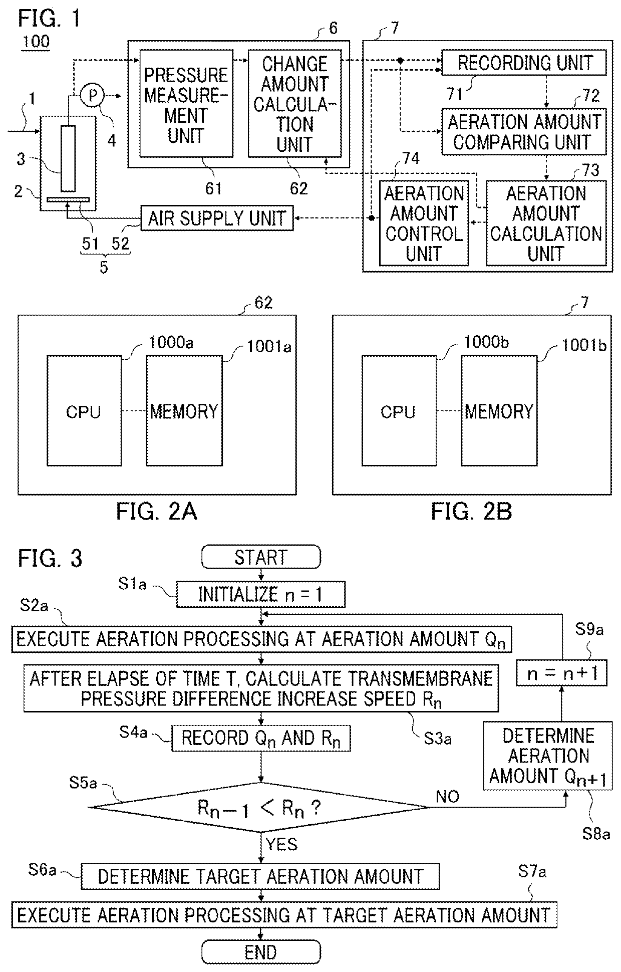
[0023]FIG. 1 is a configuration diagram of an aeration amount control system 100 according to embodiment 1. As shown in FIG. 1, the aeration amount control system 100 includes a membrane separation tank 2 into which treatment target water 1 flows, a separation membrane 3 which is provided so as to be immersed in the treatment target water 1 in the membrane separation tank 2 and filters the treatment target water 1 in the membrane separation tank 2, a filtration pump 4 for sucking treated water filtered by the separation membrane 3, an aeration device 5 for performing aeration for the treatment target water 1 toward the separation membrane 3, a measurement device 6 for measuring a change amount of the transmembrane pressure difference of the separation membrane 3, and a control device 7 for controlling the aeration amount of the aeration device 5.
[0024]The membrane separation tank 2 is configured such that the treatment target water 1 flows into the membrane separation tank 2, and a ...
embodiment 2
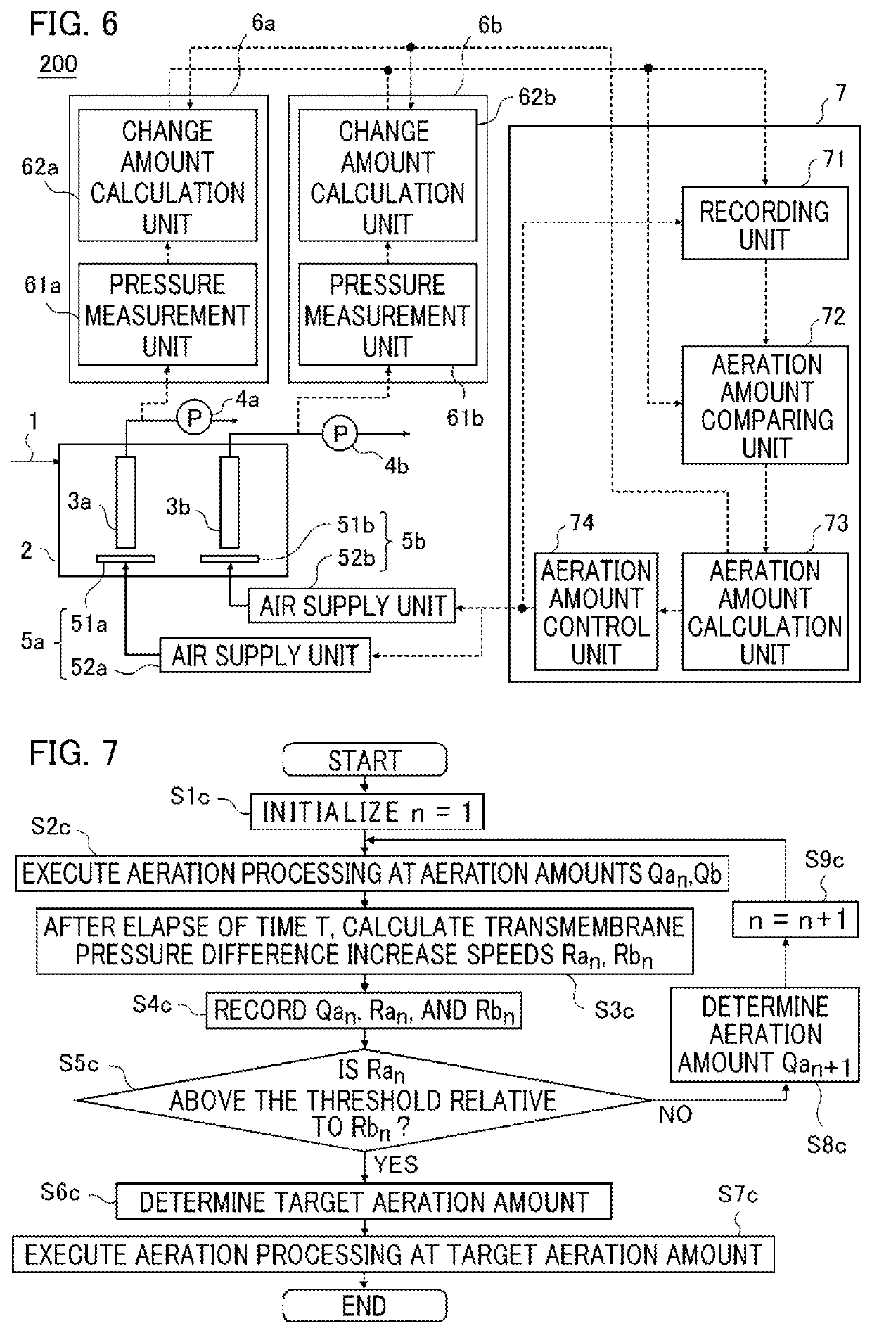
[0071]The configuration of an aeration amount control system 200 according to embodiment 2 of the present invention will be described. It is noted that the same or corresponding configurations as those in embodiment 1 will not be described and only different configuration parts will be described.
[0072]FIG. 6 is a configuration diagram of the aeration amount control system 200. The aeration amount control system 200 includes pluralities of separation membranes 3, filtration pumps 4, aeration pipes 51, air supply units 52, pressure measurement units 61, and change amount calculation units 62. It is noted that units having the same function are denoted by the same numerals followed by a, b. The other configurations are the same as those in embodiment 1, and therefore the same or corresponding parts are denoted by the same reference characters and description thereof is omitted. It is noted that the filtration system with reference numerals followed by a is defined as filtration system ...
embodiment 3
[0091]The configuration of an aeration amount control system 300 according to embodiment 3 of the present invention will be described. It is noted that the same or corresponding configurations as those in embodiment 1 will not be described and only different configuration parts will be described.
[0092]FIG. 8 is a configuration diagram of the aeration amount control system 300. The aeration amount control system 300 includes an information acquisition device 31 which acquires and stores treatment target water information. The information acquisition device 31 includes a treatment target water information acquisition unit 311 for acquiring treatment target water information and a storage medium 312 for storing the treatment target water information.
[0093]The treatment target water information acquisition unit 311 acquires, as treatment target water information, for example, the water temperature of the treatment target water 1 in the membrane separation tank 2, the mixed liquor suspen...
PUM
| Property | Measurement | Unit |
|---|---|---|
| transmembrane pressure | aaaaa | aaaaa |
| time | aaaaa | aaaaa |
| temperature | aaaaa | aaaaa |
Abstract
Description
Claims
Application Information
 - R&D
- Intellectual Property
- Life Sciences
- Materials
- Tech Scout
- Unparalleled Data Quality
- Higher Quality Content
- 60% Fewer Hallucinations
Browse by: Latest US Patents, China's latest patents, Technical Efficacy Thesaurus, Application Domain, Technology Topic, Popular Technical Reports.
© 2025 PatSnap. All rights reserved.Legal|Privacy policy|Modern Slavery Act Transparency Statement|Sitemap|About US| Contact US: help@patsnap.com