An electric current supply system, designed to be at least partially submerged in an electrically conductive liquid during operation thereof

Active Publication Date: 2020-10-15
KONINKLJIJKE PHILIPS NV
View PDF0 Cites 0 Cited by
  • Summary
  • Abstract
  • Description
  • Claims
  • Application Information

AI Technical Summary

Benefits of technology

The invention is a system for supplying electric current that prevents damage to the system in case of water damage. The system has a component that can control when the component ends its life by stopping the process of dissolving it in water. This prevents the electric current from being dumped into the water and potentially damaging other components or causing failure of power supply. The component has a gas trap portion that can help trap gas and prevent it from causing other issues. The component is made of a material that swells when exposed to water, which further helps to quickly stop the process of dumping electric current. Overall, the invention ensures safe and reliable operation of the electric current supply system.

Problems solved by technology

Another reason is that when an electric load that is arranged to be powered by means of the system receives insufficient power, this may cause damage to the electric load.
In that way, when damage occurs, it is not only possible to achieve that a dumping process of electric power to the water is automatically terminated at a certain point, but also that a dissolution process of the at least one electrically conductive component cannot continue all the way to at least one electric load connected to the electrically conductive component, for example, which would otherwise cause the electric load to be exposed to the water in the end, and / or cannot continue all the way to a junction of electrically conductive components, which would otherwise cause failure of power supply through other electrically conductive components as well.

Method used


Image

  • An electric current supply system, designed to be at least partially submerged in an electrically conductive liquid during operation thereof
  • An electric current supply system, designed to be at least partially submerged in an electrically conductive liquid during operation thereof
  • An electric current supply system, designed to be at least partially submerged in an electrically conductive liquid during operation thereof

Examples


Embodiment Construction

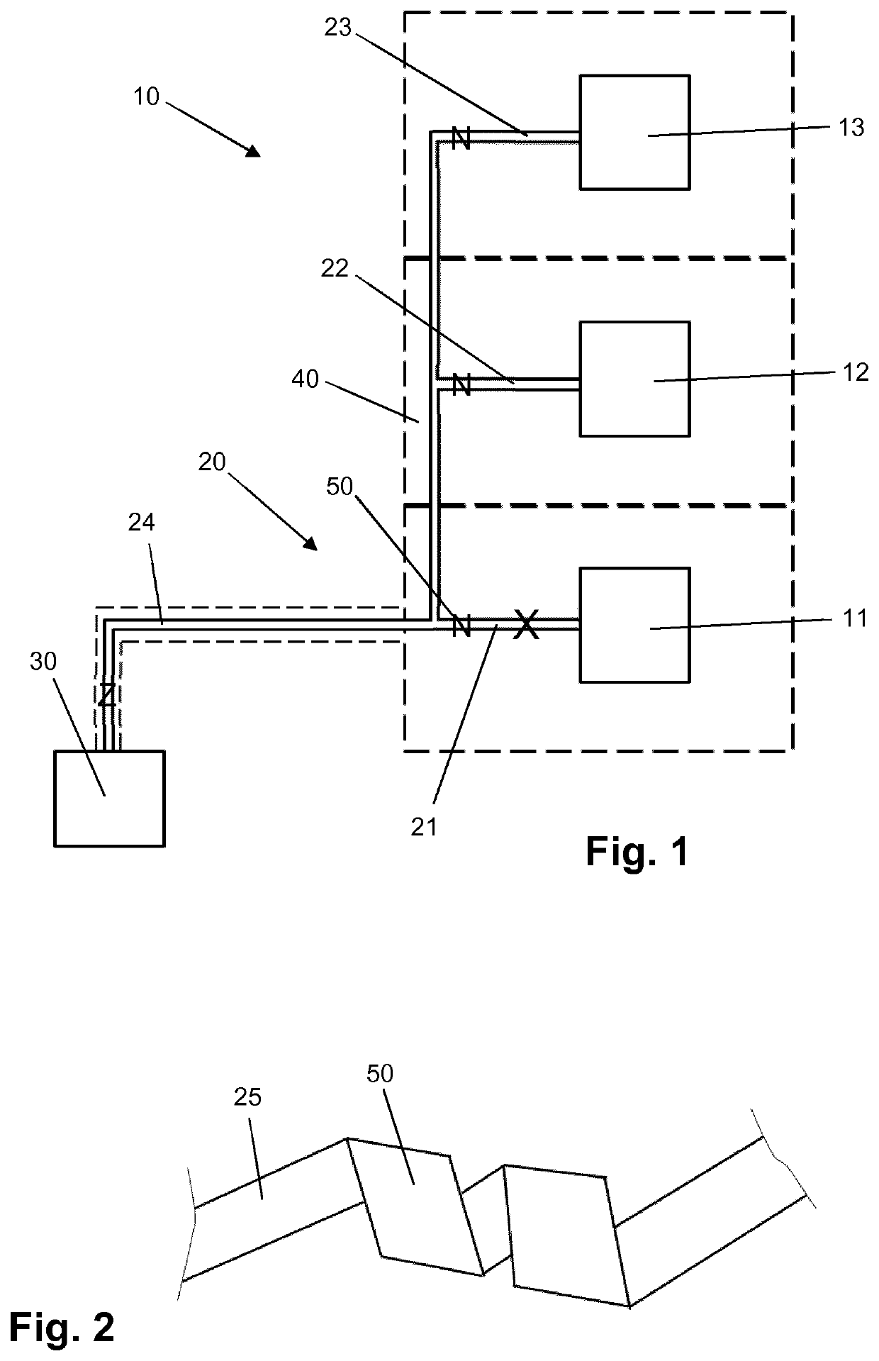
[0031]FIG. 1 provides a schematic representation of an electric device 10 comprising a number of electric loads 11, 12, 13 and an electric current supply system 20 for powering the electric loads 11, 12, 13. The number of electric loads 11, 12, 13 shown in the figure is three, which is an arbitrary number within the framework of the invention. The electric device 10 is intended to be used underwater, and may for example be arranged on a ship's hull so as to cover an area of the ship's hull. The electric loads 11, 12, 13 may be UV-C LEDs, for example, in which case the electric device 10 is suitable to be used for anti-fouling purposes, i.e. for subjecting the protected area to an anti-fouling action on the basis of which a clean appearance of the area is obtained / maintained. However, it is to be noted that the invention is not at all restricted to the field of anti-fouling, and that the present description of various aspects of the electric device 10 is equally applicable to other p...


PUM


Abstract

An electric current supply system (20) is designed to be at least partially submerged in an electrically conductive liquid during operation thereof, and comprises at least one electrically conductive component (21, 22, 23, 24) enveloped in liquid-tight material (40). The component (21, 22, 23, 24) comprises sacrificial material that is capable of reacting electrochemically with the liquid. Further, the component (21, 22, 23, 24) comprises at least one gas trap portion (50) at which the sacrificial material occupies a space in the liquid-tight material (40) that is thereby defined with a gas trapping shape. If, in case of damage to the system (20) in an actual submerged state thereof, the component (21, 22, 23, 24) gets exposed to the liquid, it is achieved that an electrochemical reaction occurring at the exposed area of the component (21, 22, 23, 24) and an outflow of electric current to the liquid are stopped.

Description

FIELD OF THE INVENTION[0001]The invention relates to an electric current supply system, designed to be at least partially submerged in an electrically conductive liquid during operation thereof, and comprising at least one electrically conductive component enveloped in liquid-tight material. The invention also relates to an electric device, designed to be at least partially submerged in an electrically conductive liquid during operation thereof, and comprising an electric current supply system as mentioned and at least one electric load connected to the at least one electrically conductive component of the electric current supply system. Another subject of the invention is an assembly of a marine object and the electric device as mentioned, the marine object comprising at least one surface that is intended to be at least partially submersed in water containing biofouling organisms during at least a part of the lifetime of the marine object, and the electric device being arranged on ...

Claims


Application Information

Patent Timeline
IPC IPC(8): C23F13/06H05B44/00
CPCC23F13/06C23F13/00H05B45/00H05B45/40H01B5/02B63B59/04A61L2/10B08B17/02B08B7/0057H01B1/023H01B1/026H01B7/12H01B17/36H01B7/2813B63B59/06B63B1/38B63B59/08B63B59/045
Inventor VISSER, CORNELIS GERARDUSVAN DELDEN, MARTINUS HERMANUS WILHELMUS MARIA
Owner KONINKLJIJKE PHILIPS NV
Why Eureka
Try Eureka