
Intubation Devices

a technology of intubation device and et tube, which is applied in the field of intubation device, can solve the problems of inability to use as sole techniques to correctly determine the placement of et tube, inability to always be possible, and difficulty, and achieve the effect of accurate visualisation and placemen

Pending Publication Date: 2020-09-24
FLEXICARE GRP LTD
View PDF0 Cites 2 Cited by
  • Summary
  • Abstract
  • Description
  • Claims
  • Application Information

AI Technical Summary

Benefits of technology

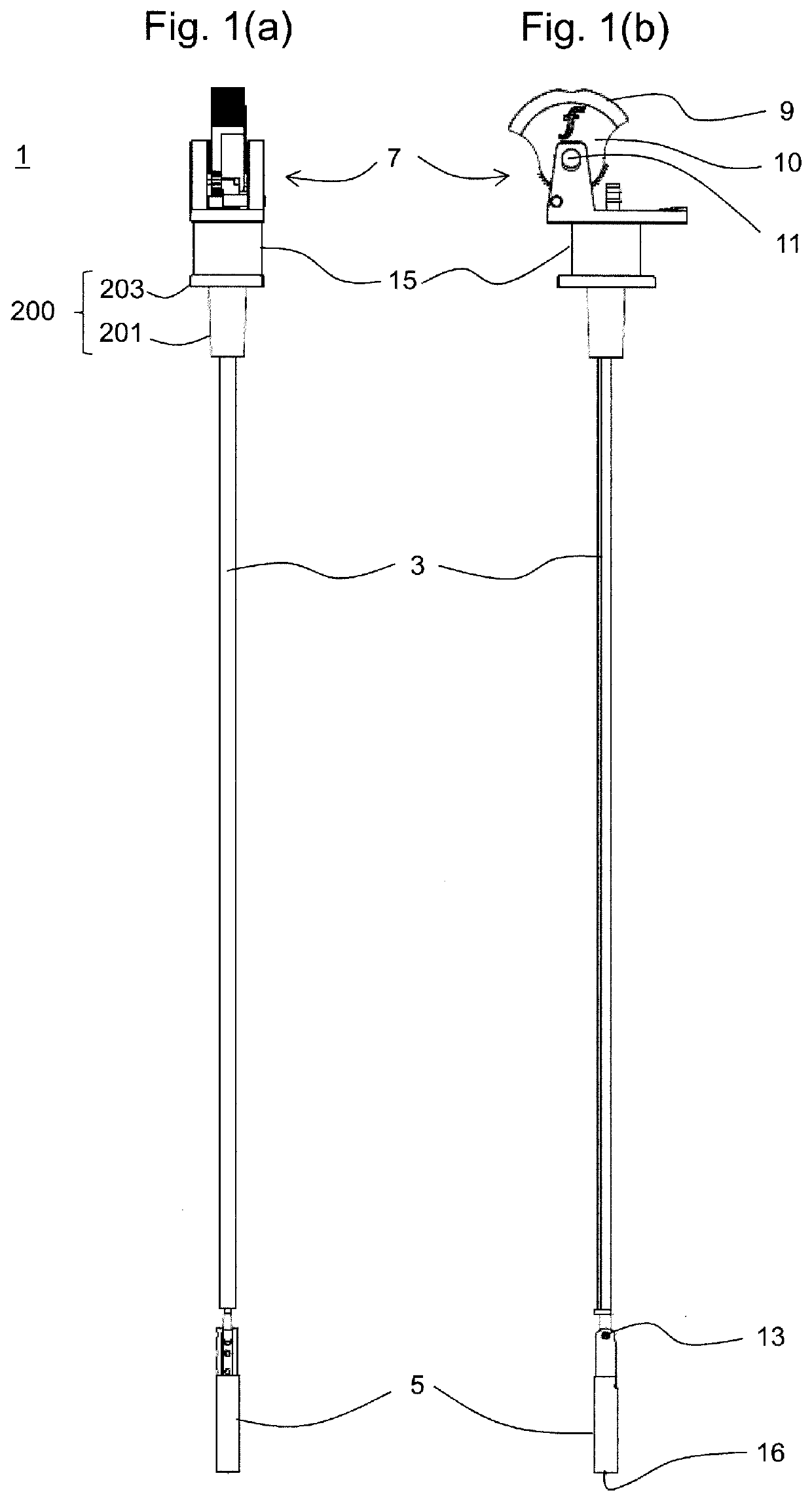
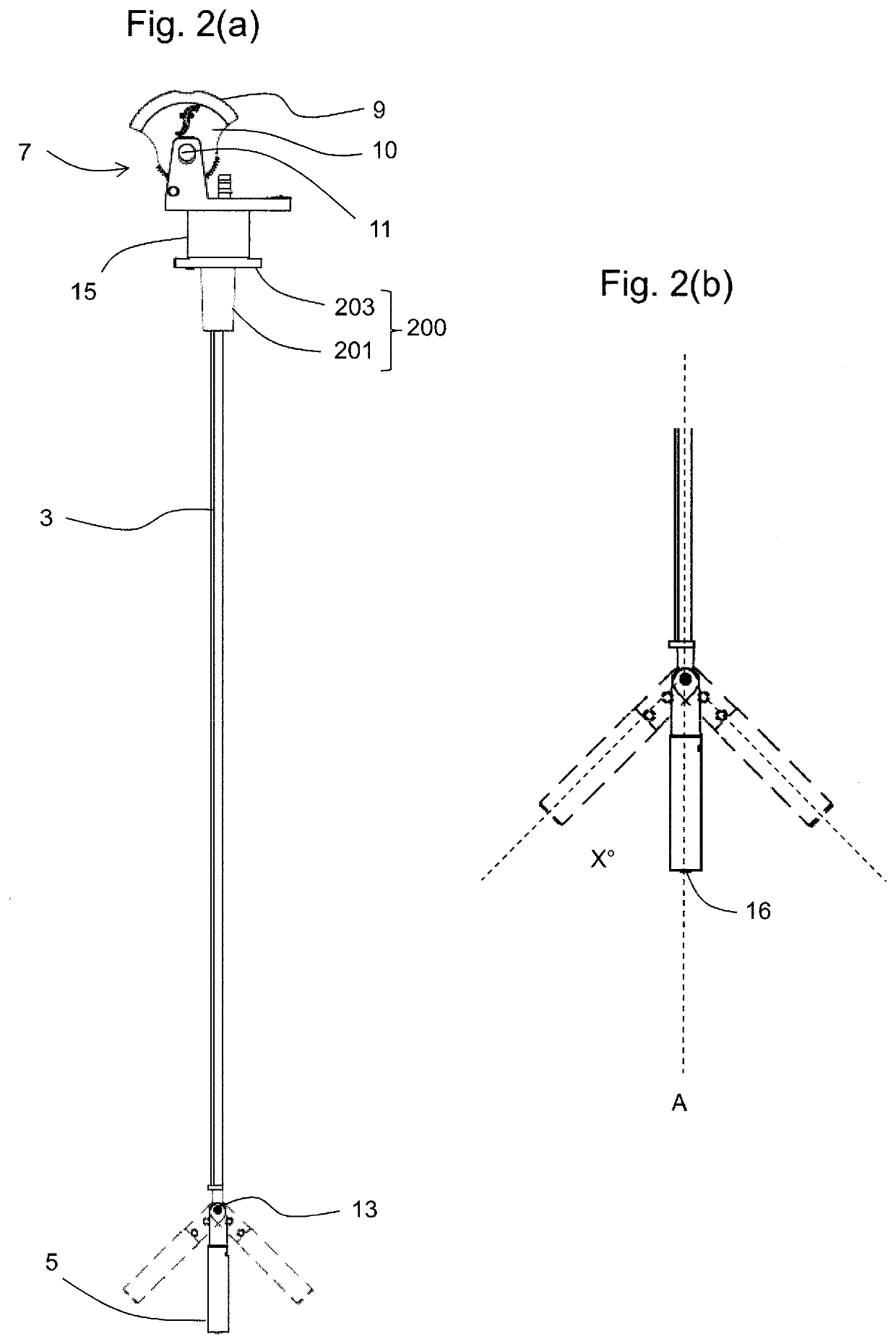
The invention proposes a stylet with a pivotable tip that allows for accurate adjustment of the direction of the tip without affecting the shape of the rest of the stylet body by e.g. additional unwanted bending along the length of the stylet. The pivotable tip is rigid and affixed to the distal end of the stylet body at a pivot hinge. The pivot range of the tip is at least ±10°, preferably at least ±20° or more preferably at least ±30°. The range of movement of the tip can be up to ±45°, ±50°, ±60°, ±70°, ±80° or ±90°. The invention allows for movement of the tip through a wider range of motion and provides more accurate control of the distal end of the ET tube during an intubation procedure.

Problems solved by technology

However, many of these methods of determining ET tube placement are not sufficiently reliable to be used as sole techniques to correctly determine ET tube location.
In some cases, the clinician performing the intubation may be able to directly visualise placement of the ET tube, but this is not always possible, depending on the particular anatomy of the patient.
For example difficulties may be encountered where the patient has restricted neck flexibility, or is obese.
However, video laryngoscopes can have drawbacks.
Also the ET tube itself may obstruct the view of the vocal cords and trachea as it advances past the end of the laryngoscope.
Video laryngoscopes tend to be expensive, which further limits their use as single use devices.
The act of placing the ET tube offers its own difficulties, even when it can be visualised clearly.
However setting the shape of the stylet before intubation can lead to undesirable delays during the intubation procedure where the set shape turns out to be not quite right for the patient's anatomy.

Method used


Image

  • Intubation Devices
  • Intubation Devices
  • Intubation Devices

Examples


first embodiment

[0054]FIGS. 7 (a-c) show an ET tube 100. The ET tube has a body 101 which comprises a flexible hollow tube. The ET tube body may typically be made from e.g. PVC, although the skilled person will be aware of a range of other suitable materials. The distal end of the tube is inserted into a patient's trachea during intubation. The proximal end of the ET tube may be removably attached to an ET tube connector for connection to a ventilation system, although this is not shown in these drawings. The ET tube has a bending portion 103 located towards the distal end 102 of the body, intermediate the body and the distal tip portion 104 of the tube. The bending portion is here formed as a concertina portion of the tube to promote preferential bending at that position. The concertina allows for increased bending of the bending portion in comparison to the general flexibility of the body of the ET tube, as demonstrated in FIG. 7 (c). The length of the concertina portion is not particularly limit...

second embodiment

[0057]FIG. 8 shows a schematic view of an ET tube. In this embodiment, the bending portion 103 is a portion of the tube made from a different material to the material of the body 101 of the tube. Here, the body of the tube is made from a first type of PVC, and the bending portion is made from a second, softer PVC, although it may also be possible to use e.g. silicone. The body and the bending portion are connected together using a seal (shown as a dashed rectangle) which extends across the join between these portions. The material chosen for the bending portion should typically be more flexible than the material of the body of the ET tube, to allow increased ease of bending the bending portion compared to the body of the ET tube. In this embodiment, the bending portion 103 includes the distal tip portion 104 of the ET tube.

[0058]In this particular embodiment, an inflatable cuff 107 is also shown. Such a cuff is a standard feature of many well-known ET tube designs, and as such, the ...


PUM


Abstract

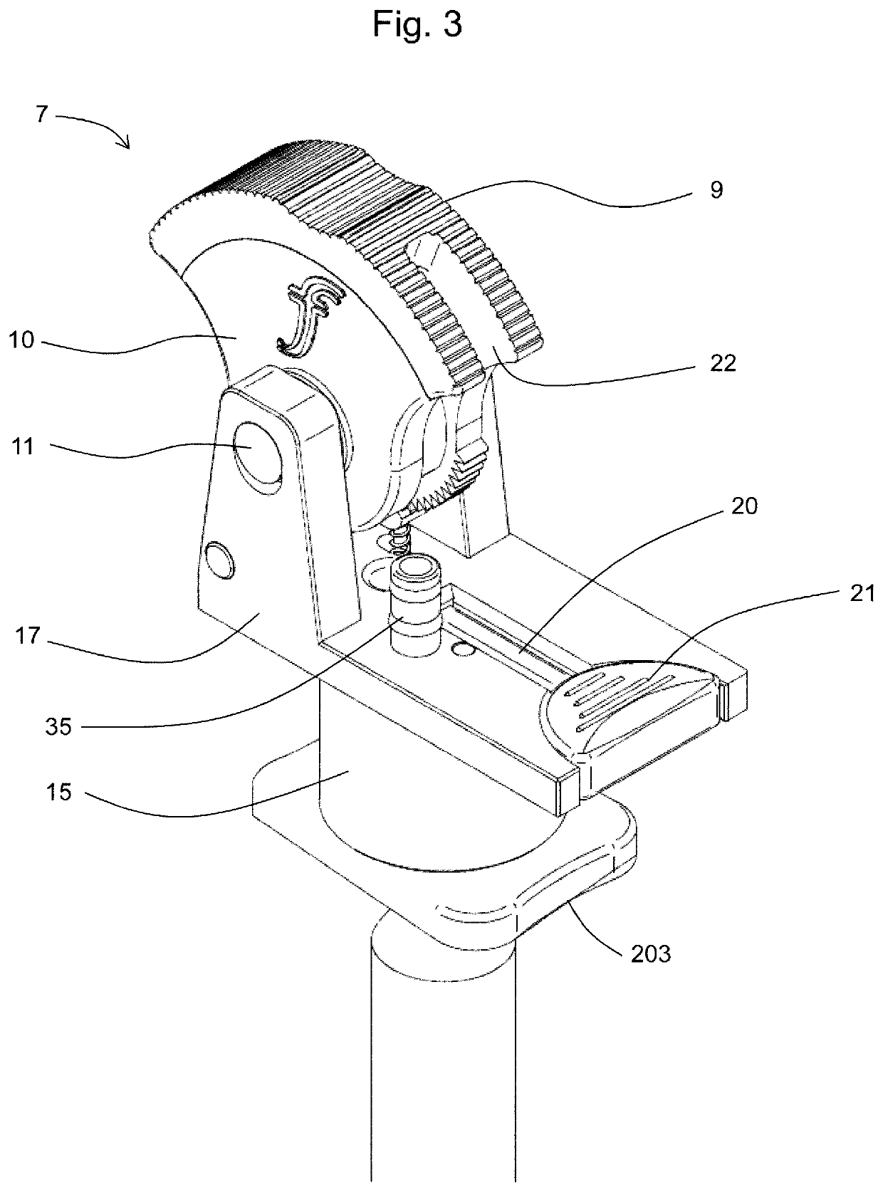
A stylet is disclosed for insertion into an endotracheal tube for guiding the tube during intubation. The stylet has a body (3) with a pivotable tip portion (5) at its distal end which is movable in either of two opposing directions away from the axis of the stylet. The tip portion (5) may carry an image acquisition device for video imaging. A control mechanism for controlling the pivot angle of the pivotable tip has a hand-operated actuator (7) at the proximal end of the stylet and flexible control wires (23) extending down the stylet to connect the actuator to the pivotable tip portion (5). Also disclosed is an endotracheal tube (100) usable with the stylet and having a bending portion (103), defined by a concertina or thinned portion, at its distal end to facilitate bending of its tip portion (104) by the stylet tip portion (5).

Description

RELATED APPLICATIONS[0001]This patent application is a national stage filing under 35 U.S.C § 371 of Patent Cooperation Treaty International Application No. PCT / EP2018 / 061216, filed May 2, 2018 entitled Intubation Devices, which claims the benefit of and right of priority to United Kingdom patent application GB1707174.7 filed May 5, 2017 and subsequently published as GB-A-2563567, the entire disclosures of each such application being expressly incorporated herein by reference.FIELD OF THE INVENTION[0002]The present invention relates to intubation devices. In particular, it relates to endotracheal tubes, and style's for use with endotracheal tubes.BACKGROUND[0003]During tracheal intubation, an endotracheal tube (ET tube) must be inserted into a patient's airway. In a typical intubation process a clinician standing above / behind the head of the supine patient will use a laryngoscope to move the tongue and epiglottis out of the way and then insert an ET tube through the patient's vocal ...

Claims


Application Information

Patent Timeline
Patent Type & Authority Applications(United States)
IPC IPC(8): A61M16/04A61M16/06
CPCA61M16/045A61M16/0672A61M16/0488A61M2205/583A61M16/0418A61M16/0463A61M2209/06A61B1/0052A61B1/01A61B1/05A61B1/008A61M16/0434
Inventor POORMAND, GHASSEM
Owner FLEXICARE GRP LTD
Learn More